13. Software Upgrade
13.1. Software Upgrade Over The Air (SUOTA)
13.1.1. Introduction
The Bluetooth low energy platform allows the user to update the software of the device wirelessly. This process is called Software Upgrade Over The Air (SUOTA) and is simple enough to be performed by the end user.
When an update procedure is initiated from an Android or iOS device, a new image is first transferred to the Firmware update partition located in the Flash memory and then the device reboots to complete the update. After the reboot is completed, the SUOTA loader transfers the image to the Executable partition and executes it. The new software version should start after the reboot with a small delay.
The SUOTA GATT server runs on the DA1468x device and the GATT client on the Android or iOS device running the SUOTA application.
13.1.2. SUOTA service description
This section gives a brief description of the SUOTA service, responsible for performing software upgrades over BLE. A detailed service characteristic description is given on Table 14.
| Characteris tic | SUOTA Version (SUOTA_VERS ION definition) |
Access | Size | Description |
|---|---|---|---|---|
| MEM_DEV | since version v1.0 | READ WRITE |
4 | Using this characteri- stic the client is able to send commands to the SUOTA service. Some of the most commonly used commands are the following:
|
| GPIO MAP | READ WRITE |
4 | Used to specify GPIO map of external FLASH device. Currently not applicable. | |
| MEM_INFO | READ | 4 | Stores the total number of bytes received until now. | |
| PATCH_LEN | since version v1.0 | READ WRITE |
2 | Specifies the number of bytes after which they are received, will send a notificatio n back to the client. This is meant to be used for flow control. The exact value is set by the client during SUOTA. The notificatio n is generated from the “STATUS” characteris tic. |
| PATCH_DATA | since version v1.0 | READ WRITE WRITE_NO_RE SP |
SUOTA v1.0, v1.1, v1.2: 120 bytes SUOTA v1.3 and later: Exact size is specified by PATCH_DATA_ CHAR_SIZE |
This is the endpoint to which SUOTA image data are sent. The default size for SUOTA versions v1.0, v1.1, v1.2 is fixed at 120 bytes. From versions v1.3 and later the exact size is specified by the “PATCH_DATA _CHAR_SIZE” characteris tic, and different values (23 – 509) can be used depending on the throughput requirement s. |
| STATUS | since version v1.0 | READ NOTIFY |
1 | This characteris tic is used to notify the client of the status of the SUOTA process. Status notificatio ns are sent to indicate error conditions (for example bad command, or CRC) or to allow flow control during SUOTA process. |
| L2CAP_PSM | since version v1.2 | READ | 2 | This is an optional characteris tic that, if it exists, indicates that the SUOTA service supports both SUOTA over GATT and SUOTA over L2CAP CoC. The value indicates the dynamic L2CAP channel on which the SUOTA service is listening for connections . The absence of this characteris tic indicates that only SUOTA over GATT is supported. |
| VERSION | since version v1.3 | READ | 1 | Indicates the version of the SUOTA service. The value is retrieved from the “SUOTA_VERS ION” definition. |
| MTU | since version v1.3 | READ | 2 | Stores the current value of the MTU, which is going to be either 23 (default), or a bigger value, if MTU exchange took place. This value can be used by the client to retrieve the MTU size (if such API is not available on its side) and write with optimal rate to the “PATCH_DATA ” characteris tic. |
| PATCH_DATA_ CHAR_SIZE | since version v1.3 | READ | 2 | Specifies the size of the “PATCH_DATA ” characteris tic. |
| CCC | READ WRITE |
1 | Client Characteris tic Configurati on. Allows the client to enable notificatio ns from the “STATUS” source. |
Once the SUOTA service is discovered on the remote device and the client
has enabled notifications by writing the CCC characteristic, the SUOTA
procedure can be started by issuing the SPOTAR_IMG_SPI_FLASH command.
The write command executes successfully only if:
- No more than one device is currently connected to the SUOTA enabled device
- The application hosted in the SUOTA enabled device allows the upgrade to take place
- There is enough memory to allocate the internal working buffers
If any of the above restrictions is violated, then command fails and an
error notification is sent back to the client (status SUOTA_SRV_EXIT).
After a successful command execution the service is able to receive data
either using GATT or L2CAP CoC layer (if the L2CAP_PSM characteristic is
available).
On SUOTA v1.3 and later, the client can use the value of the
characteristic “MTU” to perform ATT write commands to the characteristic
PATCH_DATA with optimal size if the client itself has no API to find the
optimal packet size. On previous versions the client can either retrieve
the MTU value using an OS specific command, or use the default minimum
value which is 23 bytes.
On SUOTA v1.3 and later the client can find the size of the PATCH_DATA
characteristic by reading the PATCH_DATA_CHAR_SIZE characteristic. On
previous versions the size of PATCH_DATA was fixed to 120 bytes.
Following this, the client should specify the value of the patch_len
variable by writing the PATCH_LEN characteristic. PATCH_LEN specifies
the number of bytes that once received, triggers a notification back to
the client. This kind of flow control could be used by the client to
avoid flooding the SUOTA enabled device with too much image data. The
bigger the value, the better the throughput, since notifications are
going to be generated less frequently and therefore the number of missed
connection events (where flow has stopped waiting for the notification)
is decreased.
For example, if patch_len is set to 500 bytes, notification are going to
be sent to the client when byte ranges 1-500, 501-1000, 1001 – 1500 etc.
are received. Following the Bluetooth low energy specification, the
maximum number of bytes that can be written to the PATCH_DATA
characteristic with a single ATT write command is the minimum of MTU – 3
and the size of the PATCH_DATA characteristic.
When the whole image has been sent, the client should issue the
SPOTAR_IMG_END command to indicate this to the SUOTA service. The
service is going to perform some sanity checks to verify that image
transfer took place without errors, and then it is going to generate the
appropriate status notification (SUOTA_CMP_OK on success,
SUOTA_APP_ERROR or SUOTA_CRC_ERR on error).
Finally, the client could issue an SPOTAR_REBOOT command to force a
device reboot. This step is optional, but it is highly recommended.
Note
The PATCH_DATA, PATCH_DATA_CHAR_SIZE and PATCH_LEN characteristics
are only relevant when SUOTA over GATT is taking place. When L2CAP
CoC are used, a connection should be established to the L2CAP_PSM
channel via L2CAP CoC and the flow is controlled using L2CAP credits.
SUOTA service assigns enough credits to ensure that flow won’t stop
during the upgrade. Notifications relevant to the PATCH_LEN
characteristic are not sent during image transfer, but all other
notifications are still valid.
13.1.3. SUOTA Flow
When the software update process is initiated by the SUOTA mobile application, the SUOTA-enabled application downloads the new image and reboots the system. During boot, SUOTA loader verifies the new image, copies it into the executable partition and starts execution as shown in Figure 43.
SUOTA enabled application code
The execution of a SUOTA-enabled application always starts from the same address. As a result of this during the update, the new application image is stored in a separate location in the Flash memory in the Firmware update partition. After the new image is verified, it must be copied to the Executable Flash partition. Since the application runs from Flash memory, it is impossible to safely overwrite itself with a new image, therefore this part of the update is conducted by the SUOTA loader after the reboot.
Bootloader
After each reboot, SUOTA loader checks for a valid application image in the Firmware Update partition. If a SUOTA update was performed during the previous run then the new image would have been stored in the Firmware Update partition as part of the update process. The SUOTA loader detects this new image, verifies its checksum and copies it to the Executable partition. When the copy is completed, the SUOTA loader updates the Image header partition with the new image information. Finally, the image data in the Firmware Update partition is marked as invalid so that it is ignored by the loader on a subsequent reboot.
Figure 42 and Figure 43 presents an outline of the overall SUOTA process.
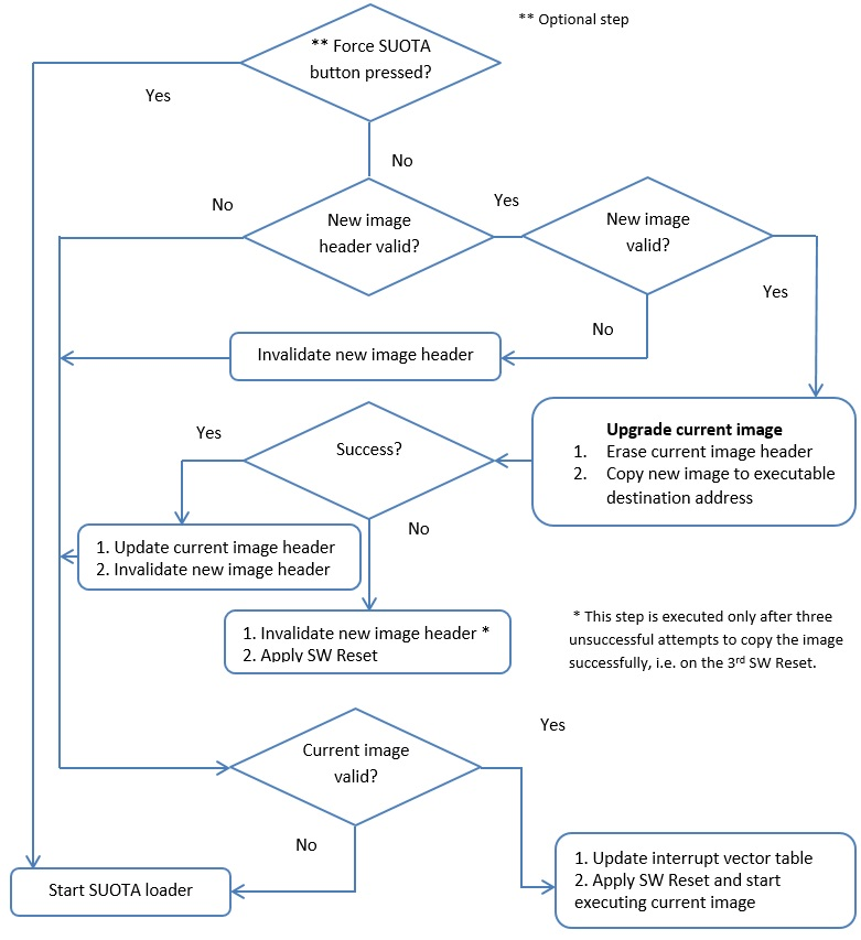
Figure 42 BLE SUOTA loader
Figure 43 BLE SUOTA Service
13.1.4. SUOTA Flash memory layout
The DA1468x platform uses partitions to divide the Flash memory into smaller sections. The NVMS layer provides unified access to those partitions. The applications can use the partition access API to read and write to the Flash memory partitions. The API also allows the modification of the size and position of partitions. The partition layout differs significantly between a SUOTA enabled build and a non-SUOTA enabled build as shown in Figure 44.
To update the software, both the SUOTA enabled application and the SUOTA bootloader need to know the location of the downloaded image in Flash memory. The following partitions are used by an application that supports software update:
- Bootloader partition, contains the bootloader that manages the update process if a new firmware executable has been uploaded.
- Product header partition (a partition with information about a device)
- Image header partition with software version information
- Application executable partition, contains the current application firmware version. In a SUOTA application this is limited to 320kB.
- Firmware update partition, this contains the new updated firmware version that the bootloader will detect on the next reboot. Practically this is limited to 320kB as well by the size of the application executable partition.
The SUOTA Partition layout is color coded in Figure 44. The yellow partitions are the ones that are modified during the update procedure, the blue partitions are accessed during the SUOTA update while green ones that remain intact throughout the update.
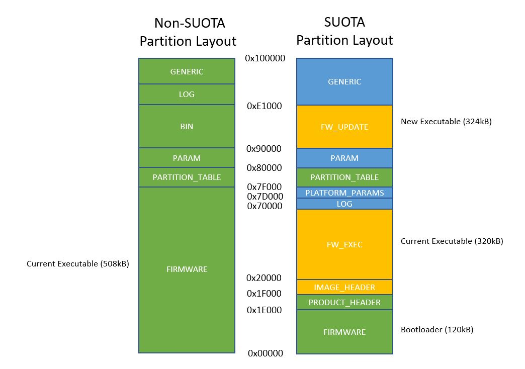
Figure 44 Flash memory partition layout comparison between SUOTA and non-SUOTA build (1Mbyte QSPI Flash)
The SUOTA Flash memory layout is defined in
sdk/bsp/config/1M/suota/partition_table.h in the ble_suota_loader
project (the non-SUOTA version is found at
sdk/bsp/config/1M/partition_table.h).
Code 9 shows how the partition table is defined in the SUOTA partition_table.h. Product and Image header description are given in Table 15 and Table 16 respectively.
PARTITION2( 0x000000,0x01E000,NVMS_FIRMWARE_PART       ,0 )
PARTITION2( 0x01E000,0x001000,NVMS_PRODUCT_HEADER_PART ,0 )
PARTITION2( 0x01F000,0x001000,NVMS_IMAGE_HEADER_PART   ,0 )
PARTITION2( 0x020000,0x050000,NVMS_FW_EXEC_PART        ,0 )
PARTITION2( 0x070000,0x00D000,NVMS_LOG_PART            ,0 )
PARTITION2( 0x07D000,0x002000,NVMS_PLATFORM_PARAMS_PART,PARTITION_FLAG_READ_ONLY )
PARTITION2( 0x07F000,0x001000,NVMS_PARTITION_TABLE     ,PARTITION_FLAG_READ_ONLY )
PARTITION2( 0x080000,0x010000,NVMS_PARAM_PART          ,0 )
PARTITION2( 0x090000,0x051000,NVMS_FW_UPDATE_PART      ,0 )
PARTITION2( 0x0E1000,0x01F000,NVMS_GENERIC_PART        ,PARTITION_FLAG_VES )
| Size | Description |
|---|---|
| 2 bytes | Container Identifier (0x70 0x62) |
| 2 bytes | Flags |
| 4 bytes | Absolute address indicating the location of the current Image |
| 4 bytes | Absolute address indicating the location of the Image Update |
| 8 bytes | Reserved |
| Size | Description |
|---|---|
| 2 bytes | FW Image Identifier (0x70 0x61) |
| 2 bytes | Flags |
| 4 bytes | Executable Size |
| 4 bytes | CRC |
| 16 bytes | Version String |
| 4 bytes | Image creation timestamp |
| 4 bytes | Executable location |
13.1.5. Performing SUOTA upgrade using a mobile phone
Note
The following procedure applies when using Android or iOS devices
The Proximity Reporter application described in section 9 can also be built with SUOTA support. To add SUOTA a different build procedure needs to be followed:
Import the following three projects into SmartSnippets™ Studio from these locations.
- scripts:
<sdk_root_directory>\utilities - ble_suota_loader:
<sdk_root_directory>\sdk\bsp\system\loaders - pxp_reporter:
<sdk_root_directory>\projects\dk_apps\demos
- scripts:
Build the two source code projects in the following configurations:
- ble_suota_loader in
DA14681-01-Release_QSPIconfiguration and - pxp_reporter in
DA14681-01- Release_QSPI_SUOTAconfiguration.
- ble_suota_loader in
Create a SUOTA image. A SUOTA image is a binary file with a proper header that can be sent to a target device from an Android or iOS device. To create the image, build PXP Reporter project, open a command prompt and navigate to
<sdk_root_directory>/projects/dk_apps/demos/pxp_reporter folderOn Windows run the MKIMAGE script with the following command (Figure 45):
> mkimage.bat DA14681-01-Release_QSPI_SUOTA
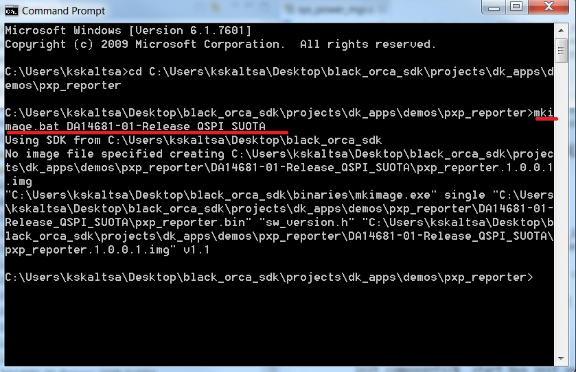
Figure 45 Run mkimage.bat script on Windows
On Linux run the mkimage.sh script with the following command (Figure 46)
$ ./mkimage.sh DA14681-01-Release_QSPI_SUOTA
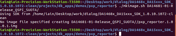
Figure 46 Run mkimage.sh on Linux
- A new image named
pxp_reporter.1.0.0.1.img, containing a version number taken fromsw_version.h, is created underpxp_reporter/DA14681-01-Release_QSPI_SUOTAfolder as shown in Figure 47
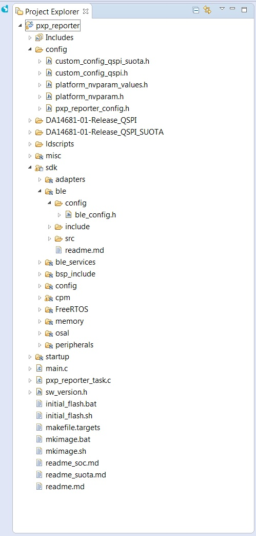
Figure 47 Project directory
Download the Dialog SUOTA application from Google PlayStore or Apple App Store.
Copy
pxp_reporter.1.0.0.1.imgto an Android phone or tablet or to an iOS device and placed into the SUOTA folder. The folder is automatically created, if it does not exist, on the device by running the “Dialog Suota” application. On Android it is located at the root directory of the “Internal Storage” drive.Erase the Flash memory of DA1468x using the
erase_qspi_jtag_winscript (to ensure the correct partition table is used) and then downloadble_suota_loaderandpxp_reporterbinaries to DA1468x usingsuota_initial_flash_jtag_winscript. This script download bothble_suota_loaderandpxp_reporterbinaries on partitionsFIRMWARE_PART(bootloader) andFW_EXEC_PARTrespectively.Press the
K2Reset button on the ProDK board. The bootloader (ble_suota_loader) should start executing the pxp_reporter image. Before executingsuota_initial_flash_jtag_winensurepxp_reporteris the selected project at “project explorer”
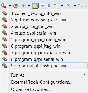
Figure 48 Scripts
- Launch the Dialog SUOTA application on the Android phone and select the DA1468x device you want to update.
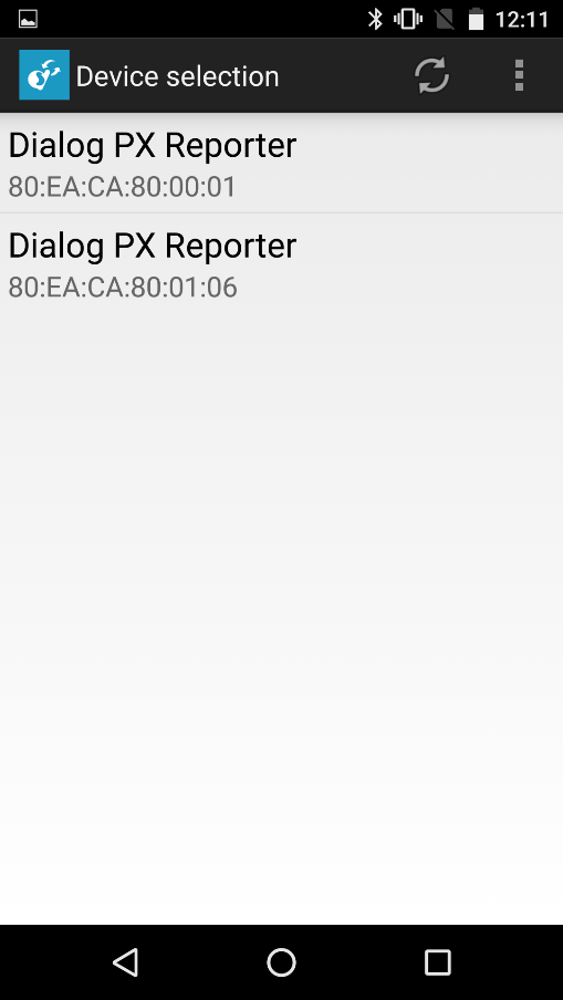
Figure 49 Device selection
- Select Update device.
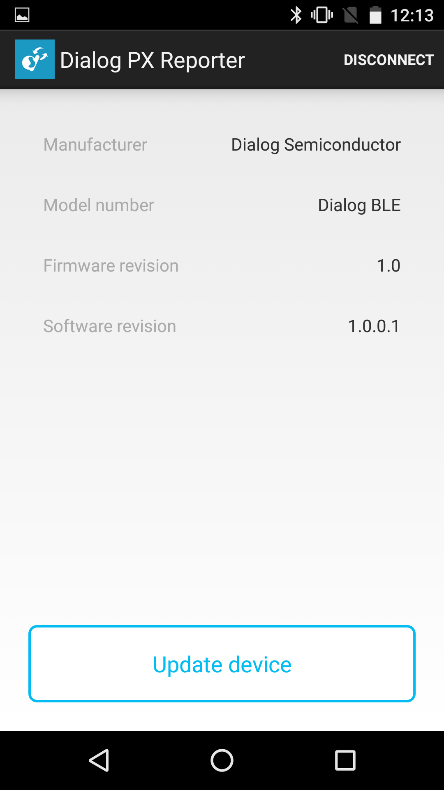
Figure 50 Update device
- Select the appropriate image file – this is a list of the files in the SUOTA directory.
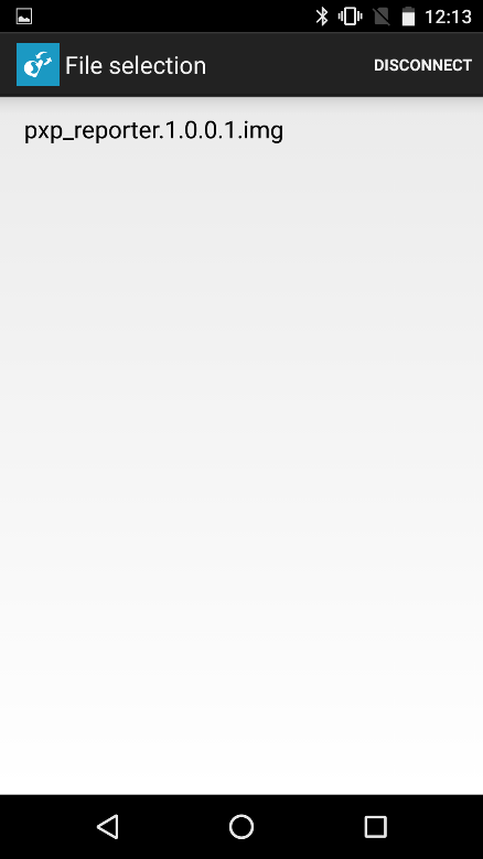
Figure 51 Image file
- Screens below are required only by DA1458x devices. For the DA1468x just press Send to device as whatever values are here have no effect.
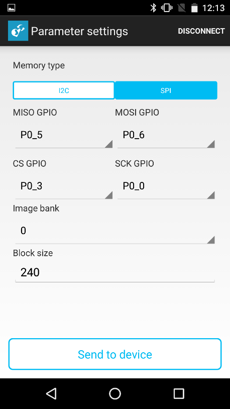
Figure 52 Parameter settings for SPI
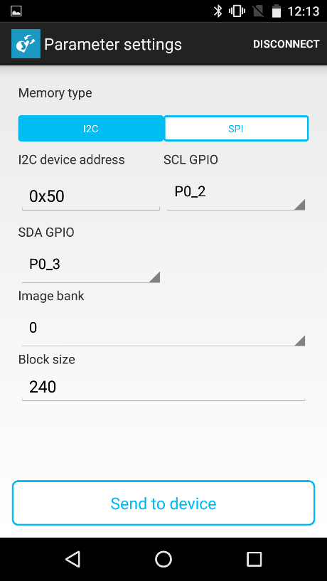
Figure 53 Parameter settings for I2C
- Wait until the process is completed. When the image is uploaded, a dialog box pops up and ask to reboot the device. Select OK.
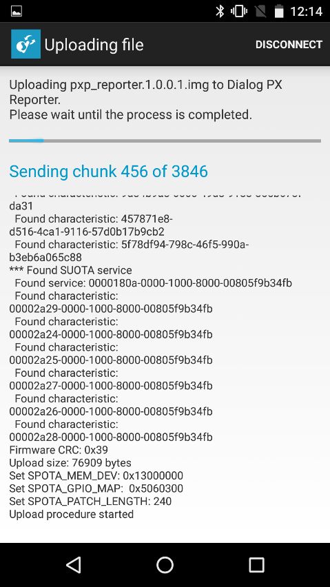
Figure 54 Uploading the image file
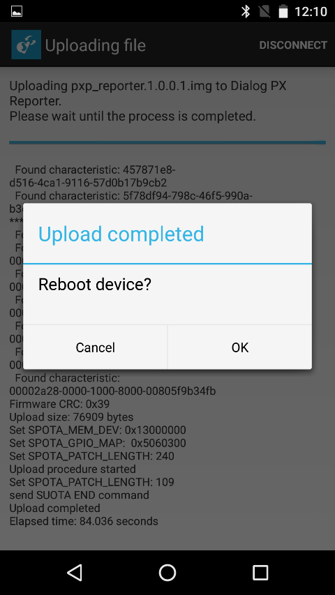
Figure 55 Reboot device
- Press Close to return to the main menu.
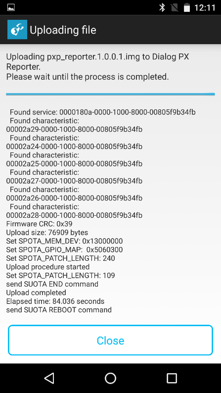
Figure 56 When file upload is finished, press “Close”
13.1.6. Performing SUOTA upgrade using two DA1468x
This section describes the procedure for performing SUOTA using two DA1468x devices.
- one acting as Bluetooth low energy central. It performs as the SUOTA
image transmitter running
ble_suota_client - one acting as Bluetooth low energy peripheral. It performs as the
SUOTA image receiver, initially running
ble_suota_loaderand after first successful SUOTA runningpxp_reporter.
Using this setup, it is possible to test both SUOTA methods (over GATT and over L2CAP Connection-Oriented Channels) without using any phone. The image to be transferred is stored in the NVMS_BIN_PART partition (Figure 44) in the Flash memory of the BLE central device.
Import the following projects using SmartSnippets™ Studio from the following locations:
- scripts:
<sdk_root_directory>\utilities - ble_suota_client:
<sdk_root_directory>\projects\dk_apps\features - ble_suota_loader:
<sdk_root_directory>\sdk\bsp\system\loaders - pxp_reporter:
<sdk_root_directory>\projects\dk_apps\demos
There are several configuration changes to the SDK required to run this demo.
To communicate successfully between the two devices they need to have different BD addresses. This can be achieved by overriding the address of the device running
ble_suota_loaderby adding this line to itsconfig/custom_config_qspi.h:#define defaultBLE_STATIC_ADDRESS {0x02,0x00,0x80,0xCA,0xEA,0x80}As delivered
ble_suota_loaderhas logging disabled, so it is difficult to track if the device is running correctly. To enable logging, change this line inconfig/custom_config_qspi.hto:#define dg_configDEBUG_TRACE 1
To enable SUOTA over L2CAP Connection-Oriented Channels (COC), both
SUOTA_VERSION and SUOTA_PSM should be defined in the
config/custom_config_qspi.h in both ble_suota_loader and pxp_reporter
images. This is done by default in SDK.
The overall architecture of the SUOTA demo is shown in Figure 57. The Central device is not enabled for SUOTA, so it is using the normal partition layout (Figure 44).
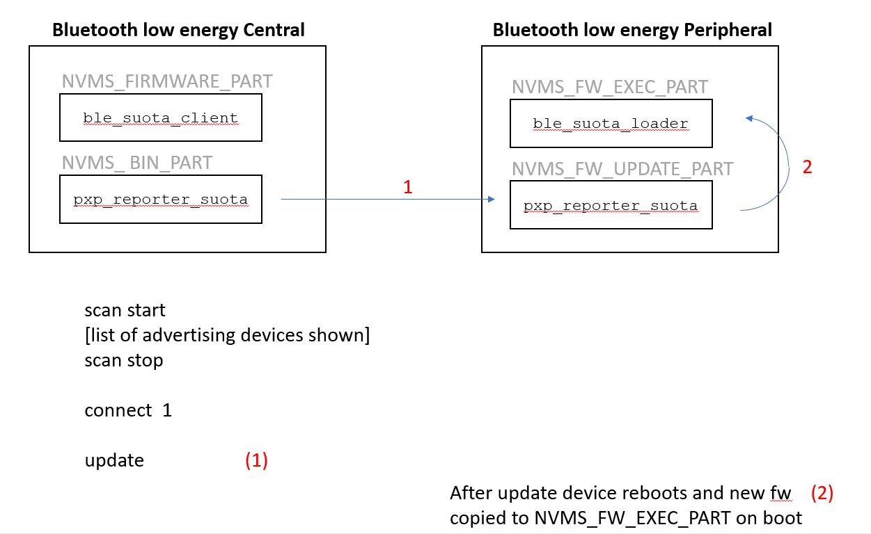
Figure 57 Dual SUOTA architecture
13.1.6.1. Building the Bluetooth low energy Central device
Select the build configuration for each of these projects
- ble_suota_client in
DA14681-01-Release_QSPIconfiguration - pxp_reporter in
DA14681-01-Release_QSPI_SUOTAconfiguration.
The aim is to program ble_suota_client into the executable partition
NVMS_FW_EXEC_PART so that it runs and then to put the update image to be
transmitted by SUOTA in the NVMS_FW_UPDATE_PART.
To prepare the DA1468x acting as Bluetooth low energy central device follow the procedure below:
- Build the project ble_suota_client (See Figure 58).
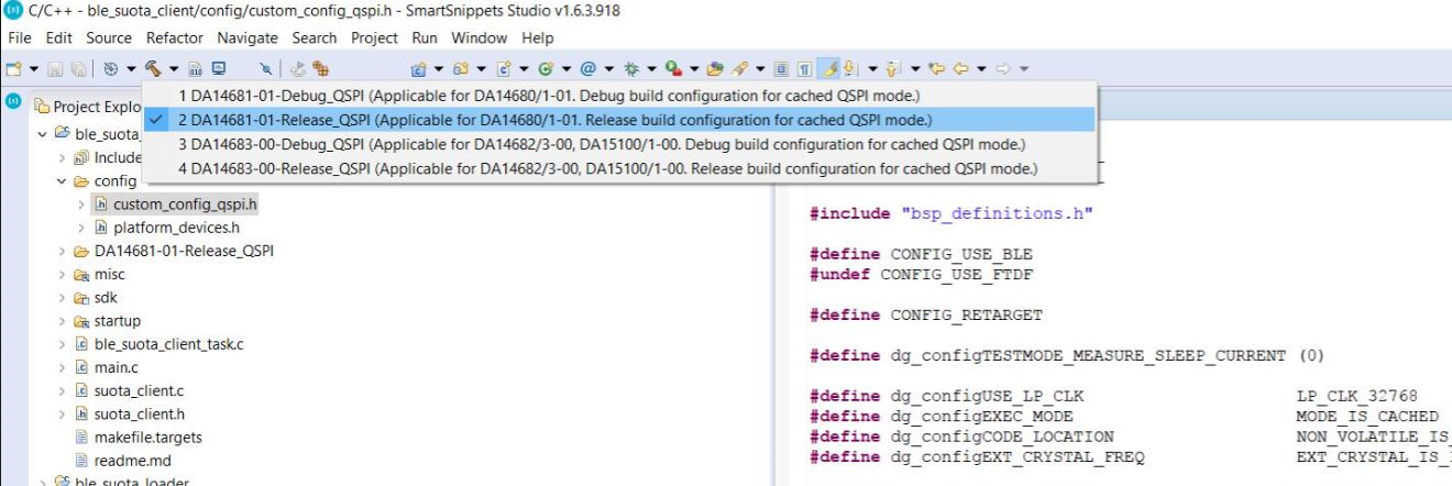
Figure 58 Building ble_suota_client
- Select the External Tool Configurations button, choose the appropriate script file (in Figure 59 the program_qspi_jtag_win script is used) to program the QSPI Flash memory and execute it.
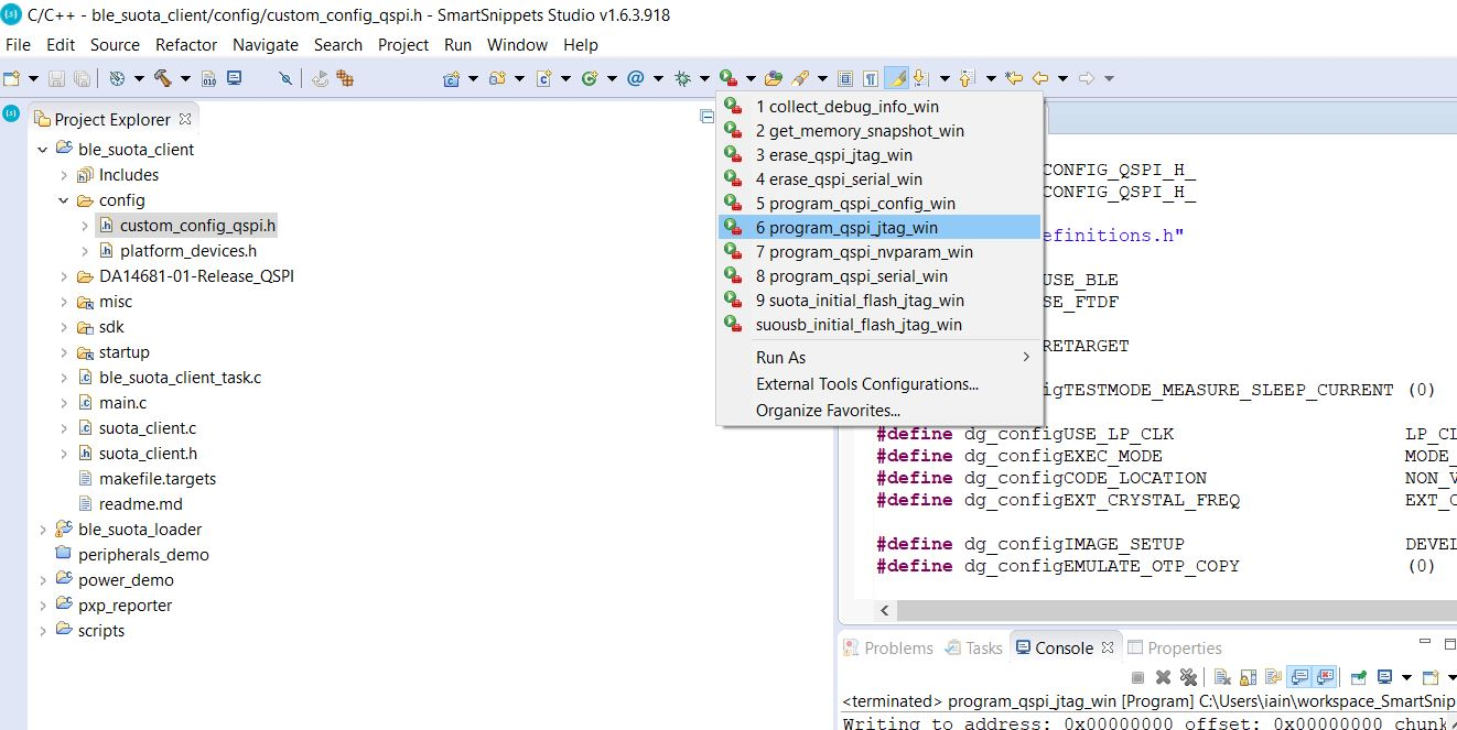
Figure 59 Flash the ble_suota_client binary to the QSPI Flash
As soon as the script is executed, a new window pops up asking to choose which of the DKs is the target; select the appropriate device.
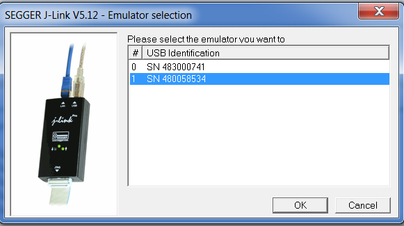
Figure 60 Selecting the target device
- Build the
pxp_reporterproject using theRelease_QSPI_SUOTAbuild configuration.
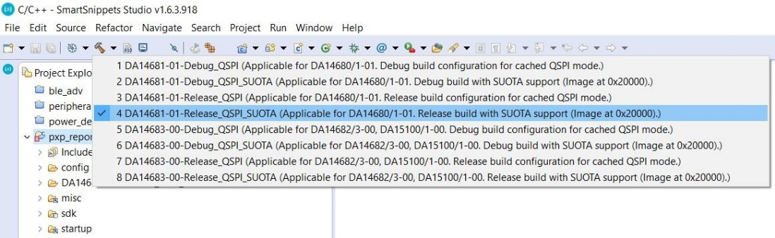
Figure 61 Building pxp_reporter for SUOTA
Create a SUOTA image. To create the image, open a command prompt, navigate to <sdk_root_directory>/projects/dk_apps/demos/pxp_reporter folder and run the following command (Figure 62) on Windows:
> mkimage.bat DA14681-01-Release_QSPI_SUOTA

Figure 62 Creating image
For Linux use the command
$ ./mkimage.sh DA14681-01-Release_QSPI_SUOTA
- Copy the image from
<sdk_root_directory>/projects/dk_apps/demos/pxp_reporter/DA14681-01-Release_QSPI_SUOTAand paste it to<sdk_root_directory>/binaries - Use
cli_programmerto download the binarypxp_reporter.1.0.0.1.imgto theNVMS_FW_UPDATE_PARTpartition. Open a command prompt, navigate to the<sdk_root_directory>\binariesfolder and run one of the following commands
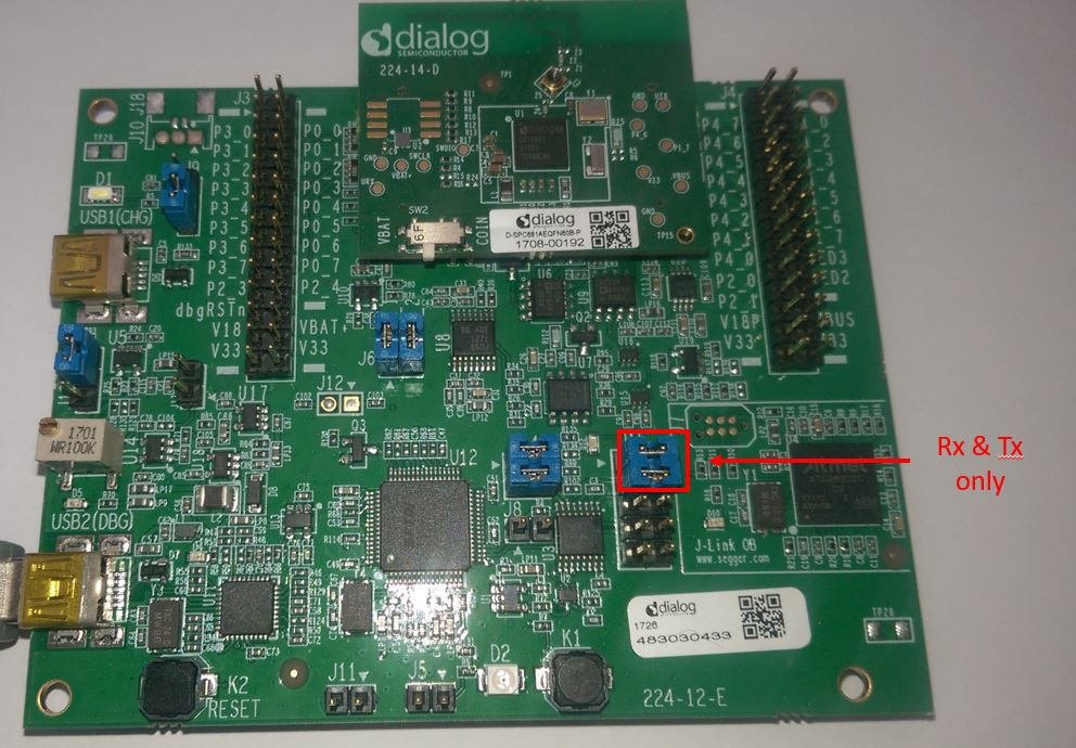
Figure 63 Jumpers only on Rx and Tx for ProDK no Flow Control
To download pxp_reporter.1.0.0.1.img using UART as shown in Figure 64.
During this procedure the user is asked to press the K2 Reset button.
> cli_programmer.exe COM13 write_qspi 0x00090000 pxp_reporter.1.0.0.1.img
To download pxp_reporter.1.0.0.1.img using SWD
> cli_programmer.exe gdbserver write_qspi 0x00090000 pxp_reporter.1.0.0.1.img
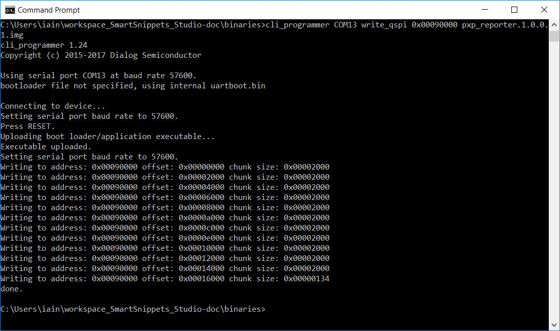
Figure 64 Uploading image to the Client
On a Linux host the equivalent commands are for a Serial download (Jumper J15.7-8 on Pro DK must not be installed for this to work)
$ ./cli_programmer.sh COM13 write_qspi 0x00090000 pxp_reporter.1.0.0.1.img
And for SWD
$ ./cli_programmer.sh gdbserver write_qspi 0x00090000 pxp_reporter.1.0.0.1.img
13.1.6.2. Building the Bluetooth low energy peripheral device
- Build the project ble_suota_loader in “DA14681-01-Release_QSPI” configuration.
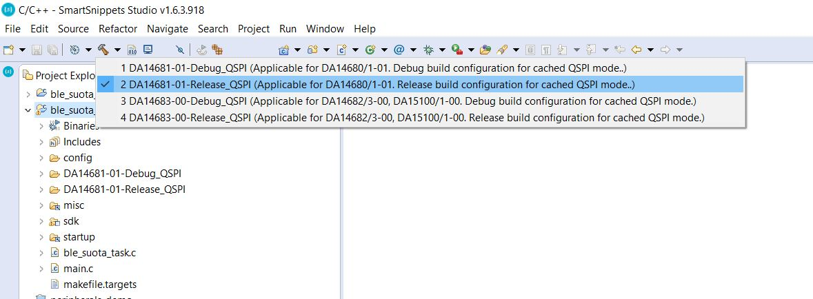
Figure 65 Building ble_suota_loader project
- Select the External Tool Configurations menu, choose the appropriate
script file (in this example, the
program_qspi_jtag_winscript is used) to program the QSPI Flash memory, and execute/run the script.
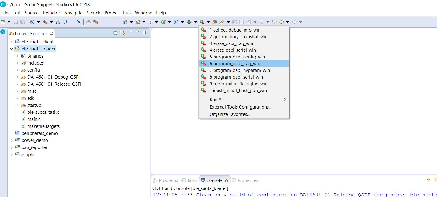
Figure 66 Flashing ble_suota_loader to QSPI Flash
As soon as the script is executed, a new window pops up asking to choose which device is the target; select the appropriate device.
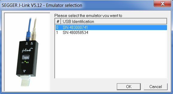
Figure 67 Selecting target device
- Press the
K2Reset button.
13.1.6.3. Running the software upgrade procedure
When the previous procedure has finished, the two DA1468x devices are ready to communicate. To load the image, the following steps should be followed.
A Pro DK running the Bluetooth low energy central device needs to have a
jumper put on J15.7-8 to connect the CTS line (Figure 68) for
ble_suota_client to run correctly. This jumper must be removed if UART
is used to reprogram a different update image with cli_programmer.
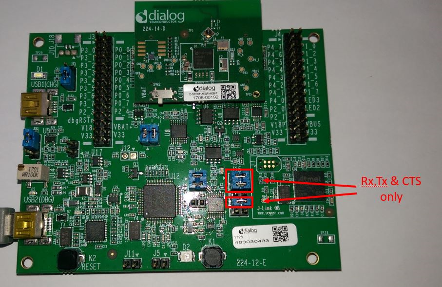
Figure 68 Jumpers on Rx, Tx and CTS
A Basic DK running the Bluetooth low energy central device needs to CTS
line driven as shown in Figure 26) for ble_suota_client to run
correctly. The jumper wire connecting CTS to GND must be removed if UART
is used to reprogram a different update image with cli_programmer.
Open two terminals, one for each device. A serial terminal is needed to control each device. In the example below, “TeraTerm” is used for this purpose
Configure serial terminal for the Bluetooth low energy central device:
- Select the serial port number for the client.
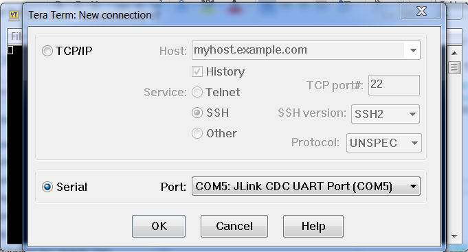
Figure 69 Specifying the serial port number
- From the Menu bar choose Setup > Serial port … and configure the serial port as 115200-8-n-1 as shown in Figure 70.
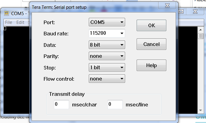
Figure 70 Configuring the serial port
- Press the
K2RESET button.
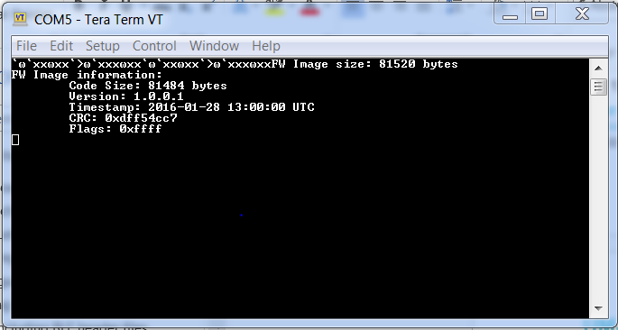
Figure 71 Information regarding the image stored in the NVMS_BIN_PART partition are displayed during boot
The Bluetooth low energy peripheral device does not have flow control on its UART so on a ProDK on the virtualCOM port configure as shown in Figure 24 and on a BasicDK with an FTDI cable connect as in Figure 15.
- Select the appropriate serial port number for the loader.

Figure 72 Specifying serial port number
- From the Menu bar choose Setup > Serial port … and configure the serial port as 115200-8-n-1 as shown in Figure 73.
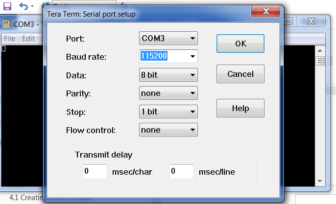
Figure 73 Configuring serial port
- Press the
K2Reset button.
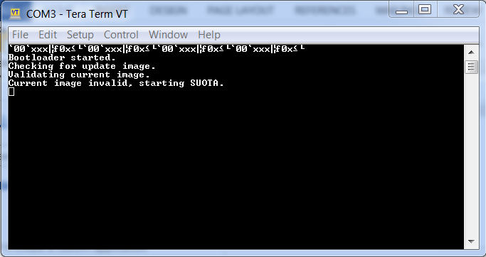
Figure 74 ble_suota_loader information is displayed during boot
In the serial terminal of the Bluetooth low energy central device, write the following command:
> scan start
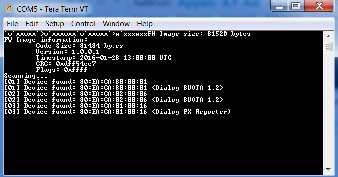
Figure 75 Scanning for available devices
The Bluetooth low energy central device starts scanning for available
devices immediately (Figure 75). In this in example, form the devices
listed Figure 75, the Bluetooth low energy peripheral device, is the
device with sequence number [01] and an advertising name of <Dialog
SUOTA 1.2>.
As soon as the Bluetooth low energy peripheral device is found, the scanning operation can be stopped with the following command:
> scan stop
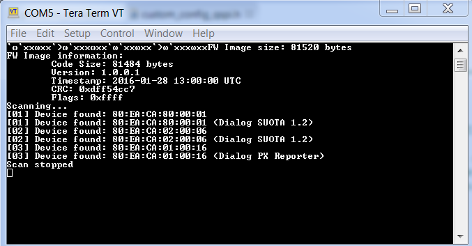
Figure 76 Stop scanning procedure
A connection to the Bluetooth low energy peripheral device can be initiated with the command:
> connect 1
The first argument of the “connect” command refers to the device index on the scan result list. Once a connection is established, the application automatically queries the remote device for available services and device information. The characteristic values of the Device Information Service (DIS) are read. The following output is printed on the terminal:
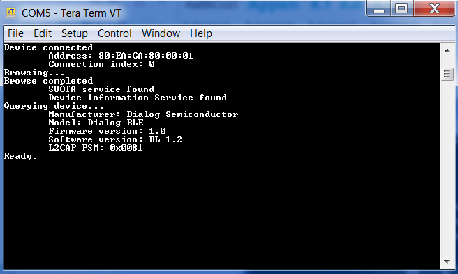
Figure 77 Connecting to loader device
The presence of “L2CAP PSM” indicates that the remote device supports SUOTA and over-L2CAP COC.
To update a device supporting L2CAP COC over L2CAP, issue the update command. To update the same device over GATT, issue the update gatt command. If the remote device does not support L2CAP COC (“L2CAP PSM” is not displayed), both update and update gatt commands begin SUOTA over GATT.
> update
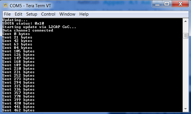
Figure 78 Updating with new image the loader device
After the image transfer has been completed, the remote device disconnects and reboot as shown in Figure 79.
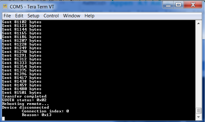
Figure 79 Transfer complete
When the Bluetooth low energy peripheral device boots, ble_suota_loader
transfers the new image from the NVMS_FW_UPDATE_PART to the
NVMS_FW_EXEC_PART partition, and execution of the new image begins.
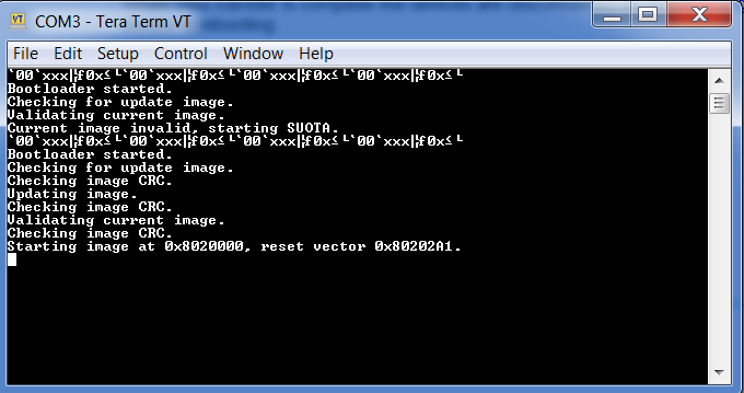
Figure 80 Rebooting and loading image
The software upgrade has finished. Now the Bluetooth low energy
peripheral device must start advertising as <Dialog PX Reporter>. To
verify that, scan again from Bluetooth low energy central device’s
terminal.
> scan start
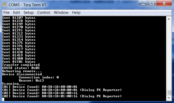
Figure 81 Verifying that loader is running PX Reporter
13.1.7. SUOTA in Production and Field deployment
When the device is deployed in the field it contains both the bootloader
(ble_suota_loader) which checks for the presence of a new firmware image
in the update partition as well as the existing application in the
execute partition (pxp_reporter in this case).
The first part of this code resides in the bootloader, where it checks
if a new firmware version is available on the update partition on every
single reboot. The second part is inside the SUOTA-enabled application.
This part decides how and when the new image can be downloaded. The user
application must broadcast the presence of the SUOTA service (using the
DIALOG SUOTA UUID) in its advertising data. The Android or IOS SUOTA
application can then identify a SUOTA capable device and initiate a
software update.
13.1.8. Recommendations
Only one SUOTA-capable Bluetooth low energy peripheral device should be connected to the Bluetooth low energy central device (e.g. an Android device running the Dialog SUOTA application) that performs a software update at any given time. If more than one device is connected to the accessory, then the SUOTA process should never be initiated. The application should decide how to handle this case.
13.2. Software Upgrade Over USB (SUOUSB)
13.2.1. Introduction
The DA1468x platform also allows the user to update the software over USB CDC. This process is called Software Upgrade Over USB (SUOUSB), and is simple enough to be performed by the end user. It can only be done on a ProDK.
The SUOUSB process starts with putting the DA1468x in SUOUSB mode, then connecting USB1 to the host PC (Windows or Linux) which then initiates the transfer of the new image to the Firmware Update partition in the Flash memory of the DA1468x. After the transfer is completed the device reboots to complete the update with the SUOUSB loader transferring the image to the Executable partition and executing it. The new software version should start after the reboot with a small delay.
13.2.2. QSPI based SUOUSB
Import the following three projects into SmartSnippets Studio from these locations.
scripts:
<sdk_root_directory>\utilitiessuousb_loader:
<sdk_root_directory>\projects\dk_apps\features\suousb_loaderpxp_reporter:
<sdk_root_directory>\projects\dk_apps\demos
13.2.2.1. Prepare bootloader
Build the suousb_loader using the DA14681-01-Release_QSPI configuration.
13.2.2.2. Prepare main image
To make the flash partition table of pxp_reporter the same with the suousb_loader project, below defines must be included:
#define dg_configIMAGE_FLASH_OFFSET (0x20000)
#define USE_PARTITION_TABLE_1MB_WITH_SUOTA
Note
The build configurations for SUOTA DA14681-01-Release_QSPI_SUOTA and DA14681-01-Debug_QSPI_SUOTA have the defines already included. These configurations can be used without any changes.
- Build the project with a configuration like
DA14681-01-Release_QSPIorDA14681-01-Debug_QSPIwith these defines changed orDA14681-01-Release_QSPI_SUOTAorDA14681-01-Debug_QSPI_SUOTAwhich has them already defined. - Erase flash entirely using
erase_qspi_jtag_win(or_linux). - Download the bootloader and the main image to flash using the script
suousb_initial_flash_jtag_win(or_linux). - The suousb_loader and
pxp_reporterprojects must be built in this order so that when the mkimage tool is run in the next stage thepxp_reporterproject was the last active project.
13.2.2.3. Prepare SUOUSB image for test
SUOUSB image is a binary file with a proper header that can be sent to a
target device from Windows and Linux. To create an image, open command
prompt in a project folder like pxp_reporter located in
<sdk_root_directory>/projects/dk_apps/features/suousb_loader and run
script to create the image file.
To build an image in Windows run:
> mkimage.bat DA14681-01-Release_QSPI_SUOTATo build an image in Linux run:
> ./mkimage.sh DA14681-01-Release_QSPI_SUOTA
It prepares an image file with the following naming format
pxp_reporter.1.0.0.1.img. The version number in the image file is taken
from file sw_version.h.
13.2.2.4. Running the SUOUSB process
The first step is to connect a USB cable from the host PC to USB1 connector on ProDK – note this is the charger USB port and not the debug one.
Put the DA1468x into USB-CDC mode by resetting the device while holding
down button K1.
Press K1 button. While it is pressed, press and release K2 RESET button.
Then release ``K1``button.
When the target enters the download mode, the messages below are shown on the serial console of host through UART if USB2 is also connected for debug.
- Bootloader started.
- Checking status of
K1Button. - K1 Button is pressed, starting SUOUSB service without booting application.
Now that SUOUSB mode has started it enumerates a USB-CDC port that
appears as another COMx port in Windows and /dev/ttyACM0 in Linux.
13.2.2.5. Transfer from a Windows host
Open a command prompt window at
<sdk_root_folder>\utilities\suousb_hostin Windows.Build using the following command:
> C:\DiaSemi\SmartSnippetsStudio\Tools\mingw64_targeting32\bin\gcc.exe -o host_usb_updater.exe host_usb_updater.c
Note
Another gcc.exe can be used. (e.g, cygwin or mingw.)
Run using the following command:
> host_usb_updater.exe 24 ..\..\..\..\..\projects\dk_apps\demos\pxp_reporter\DA14681-01-Release_QSPI\pxp_reporter.1.0.0.1.img -verboseThe number 24 is the com port number of USB-CDC device. User can see the com port number on Windows device manager.
Debug message can be enabled by
-verboseoption.
13.2.2.6. Transfer from a Linux host
Open a command terminal in
<sdk_root_directory>\utilities\suousb_hoston Linux machine.Build using the following command
> gcc -o host_usb_updater host_usb_updater.cRun using the following command
> sudo ./host_usb_updater /dev/ttyACM0 ./pxp_reporter.1.0.0.1.imgThe
/dev/ttyACM0is theusb-cdcdriver of Linux. It can be changed according to test machine.Sometimes a modemmanager in Linux system like Ubuntu might interrupt the
usb-cdccommunication. So, it should be disabled using one of the methods below.Remove the modemmanger :
> sudo apt-get remove modemmanagerDisable the modemmanger in case of usb-cdc communication by adding the rule below to
/etc/udev/rules.d/10-local.rulesATTRS{idVendor}=="2dcf", ATTRS{idProduct}=="6001", ENV{ID_MM_DEVICE_IGNORE}="1"
13.2.3. RAM based SUOUSB
Import the following three projects into SmartSnippets Studio from these locations.
scripts:
<sdk_root_directory>\utilitiessuousb_loader:
<sdk_root_directory>\projects\dk_apps\features\suousb_loaderpxp_reporter:
<sdk_root_directory>\projects\dk_apps\demos
13.2.3.1. Prepare bootloader
Build the suousb_loader using the DA14681-01-Release_RAM configuration.
13.2.3.2. Prepare main image
Prepare the main image to be downloaded and programmed to QSPI with the following steps:
To make the flash partition table of
pxp_reporterthe same with thesuousb_loaderproject, below defines must be included:#define dg_configIMAGE_FLASH_OFFSET (0x20000)``#define USE_PARTITION_TABLE_1MB_WITH_SUOTA
Note
The build configurations for SUOTA DA14681-01-Release_QSPI_SUOTA ``and
``DA14681-01-Debug_QSPI_SUOTA have the defines already included. These
configurations can be used without any changes.
- Build the project with a configuration like
DA14681-01-Release_QSPIorDA14681-01-Debug_QSPIwith these defines changed orDA14681-01-Release_QSPI_SUOTAorDA14681-01-Debug_QSPI_SUOTAwhich has them already defined. - Erase flash entirely using
erase_qspi_jtag_win(or_linux). - Download the bootloader and the main image to flash using the script
suousb_initial_flash_jtag_win(or_linux). - The suousb_loader and pxp_reporter projects must be built in this
order so that when the mkimage tool is run in the next stage the
pxp_reporterproject was the last active project.
13.2.3.3. Prepare SUOUSB image for test
SUOUSB image is a binary file with a proper header that can be sent to a
target device from Windows and Linux. To create an image, open command
prompt in a project folder like pxp_reporter located in
<sdk_root_directory>/projects/dk_apps/features/suousb_loader and run
script to create the image file.
To build an image in Windows run:
> mkimage.bat <build_configuration>
Where build_configuration may be DA14681-01-Release_QSPI,
DA14681-01-Debug_QSPI, etc.
To build an image in Linux run:
> ./mkimage.sh <build_configuration>
Where build_configuration may be DA14681-01-Release_QSPI,
DA14681-01-Debug_QSPI, etc.
It prepares an image file like pxp_reporter.1.0.0.1.img. The file name
contains a version number taken from file sw_version.h.
13.2.3.4. Running the SUOUSB process
The first step is to connect a USB cable from the host PC to USB1 connector on ProDK – note this is the charger USB port and not the debug one.
To enter the download mode user should follow the next steps:
- Load suousb_loader into RAM using RAM script.
- suousb_loader should be paused at break point of the main function.
- Press ``K``1 button of board and select resume debug mode in SmartSnippets™ Studio.
- Now that SUOUSB mode has started it enumerates a USB-CDC port that
appears as another COMx port in Windows and
/dev/ttyACM0in Linux.
Everything else is the same as in the QSPI based SUOUSB and the windows and linux host download instructions are the same as in the QSPI based SUOUSB in sections 13.2.2.5 and 13.2.2.6.
13.2.4. Use both SUOUSB and SUOTA
SUOUSB and SUOTA can be enabled together in the image. The SUOUSB is
applied to the bootloader (suousb_loader) while SUOTA is applied to the
main image e.g. pxp_reporter. For the preparation of the bootloader
and the main image please follow the steps described in the
corresponding sections of the SUOSB and SUOTA.