10. Peripheral Demo Application
This sample application shows how to use the drivers for the main peripherals on the DA1468x family of devices.
10.1. Basic services and features
This application demonstrates using device peripherals on the Dialog DA1468x Platform.
- The application is controlled using text-based menu via UART1 which is accessed through the virtual COM port over USB on Pro DK (ensure jumpers are fitted on J15.1-2 and 3-4). On the Basic DK it must be accessed via an RS232-TTL level converter cable such as an FTDI TTL-232R-RPi. This demo does not use flow control and so the FTDI cable must be connected as follows. The orange wire is connected to P1_3 (Rx), the yellow wire is connected to P2_3 (Tx) and the black wire is connected to GND (J4.2). There must also be no jumpers on J13. This is shown in Figure 15.
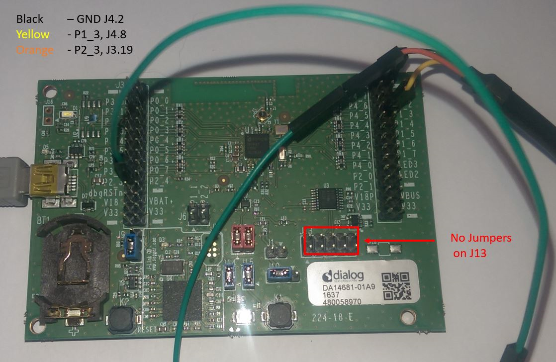
Figure 15 FTDI cable connected to UART on Basic DK with no flow control
- Some demos emit debug messages that are only visible only via UART2,
- Almost all peripherals are exercised by this application.
On both Pro and Basic DK UART2 must be accessed using an RS232-TTL level
converter cable such as an FTDI
TTL-232R-RPi or a
UART-USB conversion module to connect to the host PC.
Figure 16 shows a FTDI TTL-232R-RPI cable connected to UART2. The orange wire is connected to P4_1 (Rx), the yellow wire is connected to P4_2 (Tx) and the black wire is connected to GND (J4.1).
The actual function of these pins (P4_1 and P4_2) is controlled by the
function periph_setup() which sets the pin multiplexing.
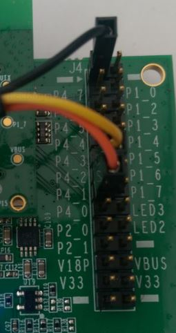
Figure 16 Connecting USB-UART cable to UART2
10.2. User Interface
The DK is connected to a PC running windows using a USB cable which is
used to power the development kit. On the Pro DK it is also used to
provide a virtual COM port to transfer data between a serial terminal
running on the PC and the peripherals_demo application running on the
DA1468x using UART1. On the Basic board UART1 is accessed directly from
the Breakout header
When the application starts a menu appears on the terminal application
on the host that allows the user to interact with the peripherals_demo
executable running on the DK.
The peripherals_demo was written to run on the DK development kit for
the DA1468x family of devices. Figure 17 illustrates the general setup
of the project.
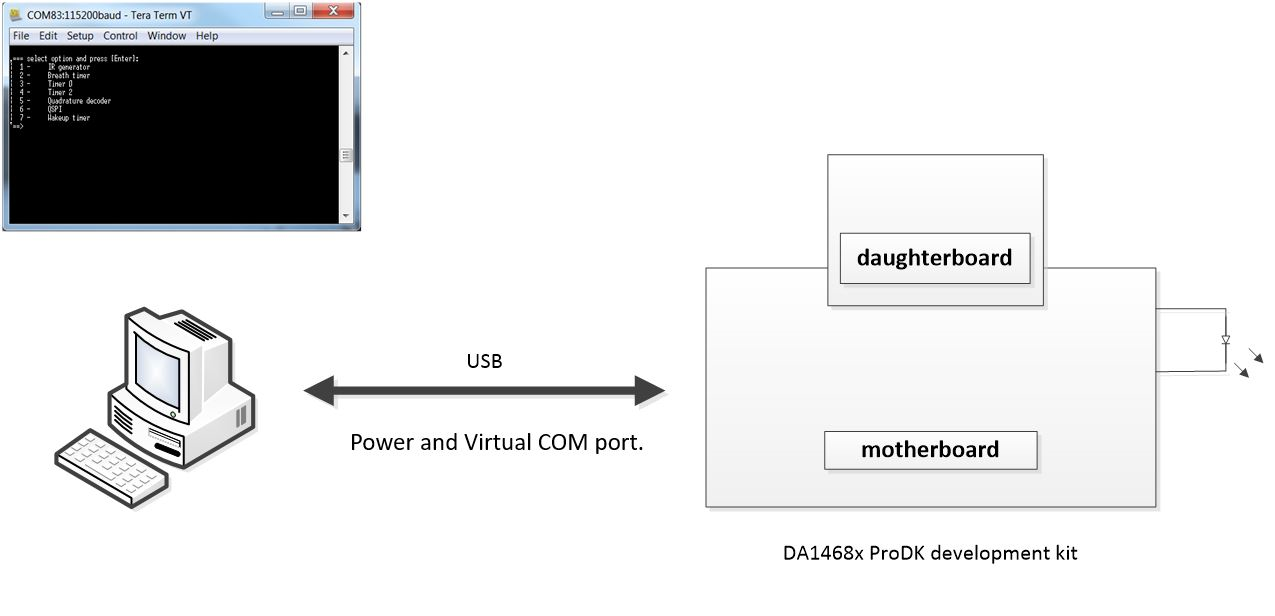
Figure 17 peripherals_demo – system overview
10.3. Importing the project
The user must import the project into the Project Explorer of
SmartSnippets™ Studio. To import the project located in
<sdk_root_directory>\projects\dk_apps\demos\peripherals_demo folder do
the following steps:
- Start SmartSnippets™ Studio by double clicking to the icon located in the Desktop.
- Go to File > Import > General > Existing Projects into Workspace and click Next.
- Find the folder containing the project is located:
<sdk_root_directory>\projects\dk_apps\demos\peripherals_demoand click OK. - Tick
peripherals_demo. - Click Finish.
10.3.1. Building the project
The Peripheral Demo Application project, like all other Bluetooth low energy projects, comes with a built-in configuration for QSPI cached execution mode. The project can be built using either the DA14681-01-Debug_QSPI or the DA14681-01-Release_QSPI configuration. This is done by selecting the project and clicking on the Build button on the SmartSnippets™ Studio toolbar as shown in Figure 18 or right click on the project’s name and select Build Project from the pop-up menu.
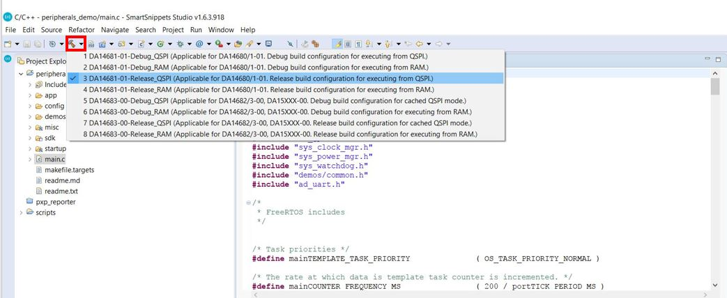
Figure 18 Building the project in Release_QSPI mode
10.3.2. Programming the QSPI Flash
- Select the project folder and click on the icon as shown Figure 19 and make active the build mode that you want to be programmed to the QSPI Flash memory.
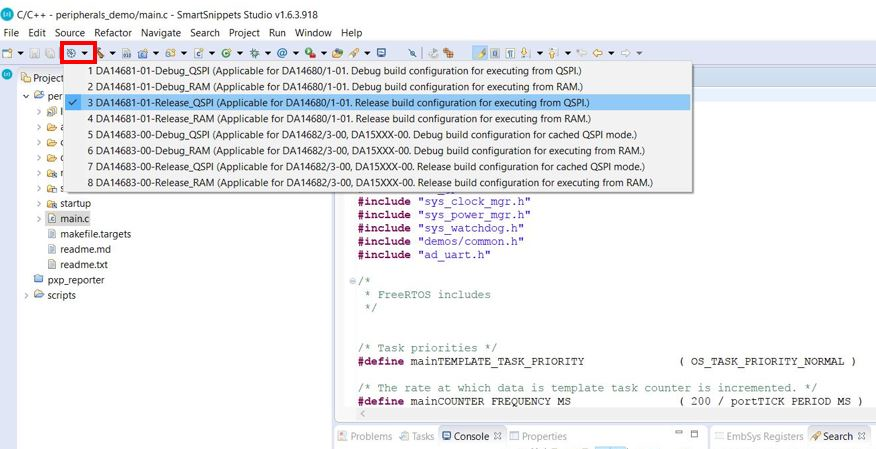
Figure 19 Selecting build mode to be programmed
- Under the External Tool Configurations menu, click on the
program_qspi_serial_winoption as shown in Figure 20 (Or Run > External Tools > program_qspi_serial_win).
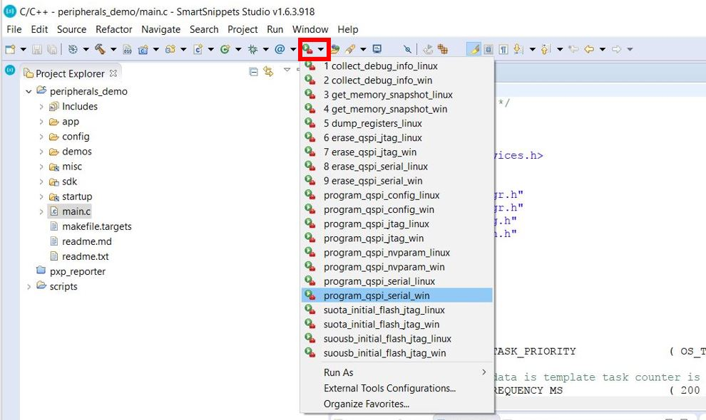
Figure 20 Program the QSPI Flash
10.4. Interacting with the Application
- Open the Terminal program on the host PC. These instructions are for
TeraTerm on Windows. Configure TeraTerm by selecting
‘serial’, then navigate to‘Setup’and select‘Serial port..’and configure it with the parameters as shown in Figure 21.
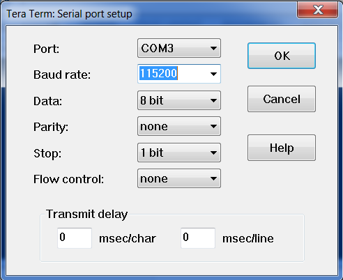
Figure 21 Configuration of the Serial Terminal
- On a Linux Host connect the terminal program to
/dev/ttyUSB0and use the same serial port configuration options shown in Figure 21. - In TeraTerm it is necessary to enable local echo so that the commands typed on the Host PC appear in the terminal. Configure TeraTerm using Setup > Terminal and then tick local echo as shown in Figure 22.
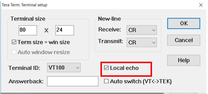
Figure 22 Enable local echo in TeraTerm
- Press
K2Reset button on the DK board to start the application.
When the serial terminal adapter has been correctly set up and the
peripherals_demo has been started, the following screen (Figure 23)
should appear in the terminal:
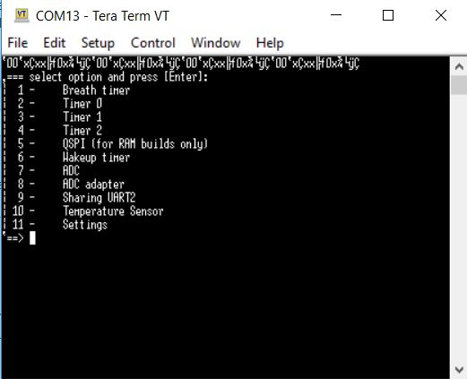
Figure 23 Output in serial terminal
User is now able to select an option by inserting a number in the terminal and then pressing the Enter key. There are a couple of things to note
- the menu may differ depending on which demos have been selected in the project’s configuration.
- The first line in terminal is the Boot ROM transmitting its name at a different baud rate (57k)
Entering a number either initiates the execution of the selected option or shows a prompt to a submenu with more options. In this way, users can interact with the application.
It should be stated here that the peripherals_demo project is only able
to evaluate peripherals that are found on the DK board and do not
require additional hardware. In order to test additional hardware
components such as those on the sensor board, the peripherals_demo
project needs to be properly configured.
These additional components are enabled in the userconfig.h file,
located in config/default folder as shown in Code 7. After rebuilding
the project, the UART menu, shown above, is extended with the newly
defined demo functionality. It is recommended to copy
config/default/userconfig.h to config/userconfig.h and make any changes
there. This file overrides the default one during building.
/*
 * Below you can enable or disable devices demos for demo_sensors.
 * They require a sensor board.
 *
 * HW_GPADC, AD_GPADC and HW_TIMER2 demos should be disabled to use sensors demos which use I2C
 * interface for communication with the motherboard.
 */
   #define CFG_DEMO_SENSOR_BH1750  (0)
   #define CFG_DEMO_SENSOR_BME280  (0)
   #define CFG_DEMO_SENSOR_ADXL362 (0)
   #define CFG_DEMO_SENSOR_BMM150  (0)
   #define CFG_DEMO_SENSOR_BMG160  (0)