17. Optimizations
17.1. Optimize BLE framework footprint
This section describes macros that can be used to reduce the application image size. Usually an application implements only one of the supported Bluetooth low energy roles (for example it is only central or peripheral), so code relevant to unused Bluetooth low energy roles can be excluded from the final build. Additionally, most of the time a Bluetooth low energy application would be a GATT server or a GATT client, and therefore extra functionality can be removed. Table 50 shows the available preprocessor macros that could be used to reduce the footprint of the user application.
| Macro | Default | Description |
|---|---|---|
| dg_configBLE_PERIPHERAL | 1 | Set to 0 if the application is not using BLE-peripheral related code. |
| dg_configBLE_CENTRAL | 1 | Set to 0 if the application is not using BLE- central related code. |
| dg_configBLE_OBSERVER | 1 | Set to 0 if the application is not using BLE-observer related code. |
| dg_configBLE_BROADCASTER | 1 | Set to 0 if the application is not using BLE-broadcaster related code. |
| dg_configBLE_GATT_CLIENT | 1 | Set to 0 if the application is not using GATT client related code. |
| dg_configBLE_GATT_SERVER | 1 | Set to 0 if the application is not using GATT client related code. |
| dg_configBLE_L2CAP_COC | 1 | Set to 0 if the application is not using L2CAP connection oriented channels related code. |
Note
All macros are defined as 1 (enabled) by default. To disable a macro define it as 0 in the project custom configuration file config/custom_config_qspi.h so that it will override the default setting.
FAs an examp Code 38 shows the Macros that are defined as 0 to optimize the BLE framework footprint in the pxp_reporter demo application as it only needs to be a peripheral and run a GATT server.
application.
/**
 * BLE device config
 */
#define dg_configBLE_CENTRAL                    (0)
#define dg_configBLE_GATT_CLIENT                (0)
#define dg_configBLE_OBSERVER                   (0)
#define dg_configBLE_BROADCASTER                (0)
#ifndef SUOTA_PSM
#define dg_configBLE_L2CAP_COC                  (0)
17.2. Optimizing FreeRTOS heap usage
This section discusses optimizing the FreeRTOS heap. The OS heap is a RAM buffer reserved for all dynamically allocated objects. This section focuses on how to profile FreeRTOS heap usage so that the configured heap size is optimal.
17.2.1. FreeRTOS Memory Management
Every application based on FreeRTOS must select and use the FreeRTOS
memory management module. This memory management module enables objects
to be dynamically allocated (by calling FreeRTOS pvPortMalloc()
function) and eventually freed (by calling pvPortFree() function).
The FreeRTOS distribution provides four memory management implementations with different features and trade-offs: heap_1, heap_2, heap_3 and heap_4.
The SDK uses heap_4. This scheme permits memory to be freed, implements a simple first-fit algorithm with a coalescence algorithm that combines adjacent freed blocks into a single large block. More information about the various FreeRTOS heap_x modules can be found on www.freertos.org.
All dynamically allocated objects (allocated using pvPortMalloc() function) are taken from a fixed size buffer. This buffer is the FreeRTOS Heap.
The OS Heap size is defined statically in each application configuration file. Heap size is application dependent; hence each application requires a different size for the OS Heap. On one hand, the OS Heap must be big enough to support dynamic allocated memory requirements. On the other hand, the Retention Memory budget impacts Power Consumption while sleeping, so heap needs to be minimized. The goal is to have just enough heap memory allocated for the application.
FreeRTOS Heap contains the OS execution contexts of the application tasks so it needs to be retained. A look at the map file (*.map) generated during build, shows the amount of data retained by heap_4.o module (the SDK redefines privileged_data to mean data that needs to be in retained RAM section 10.1.3). The application privileged_data is the major part of the retained memory budget, with the remainder being retained static variables from other modules like tasks, queues and timers.
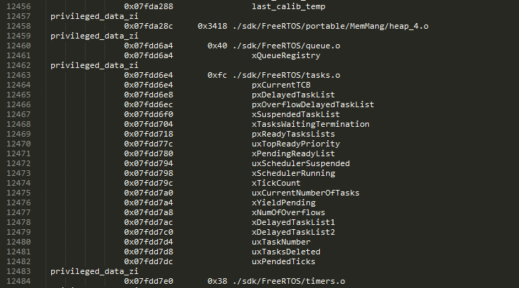
Figure 76 Amount of data retained by the heap_4.o module
| FreeRTOS | Retention | |
|---|---|---|
| Code | Data | |
| heap_4.o | 0 | 13336 |
| queue.o | 0 | 64 |
| tasks.o | 0 | 252 |
| timers | 0 | 56 |
| ad_nvms_ves.o | 0 | 4 |
| Total | 0 | 13712 |
17.2.2. OS Heap & Tasks Stack size
OS Heap Size is application dependent. In FreeRTOS whenever a heap allocation cannot be serviced, the hook vApplicationMallocFailedHook() is called to handle the error.
In addition to the heap, each Task created by the application requires its own stack. The stack is allocated form the heap and its size should be:
- Big enough so that its stack pointer remains in the stack. FreeRTOS checks on every context switch whether the stack has overflowed and calls
vApplicationStackOverflowHook()when an overflow is detected. - As small as possible, so that Power Consumption while sleeping is limited (section 17.3).
The size of the required stack varies according to the number of nested function calls, the number of parameters that are passed in function calls and the number and the type of local variables in functions.
If the “worst case” execution path is known, it might be easy to calculate the optimal stack size for a task. However, knowing this “worst-case” execution path is not always simple, so a more practical method is proposed in the next paragraph.
17.2.3. Optimizing FreeRTOS Heap
The following steps describe a practical and empirical approach to the optimization of the FreeRTOS Heap memory.
Step 1:
For every task, the application developer should continuously monitor and optimize stack size. This should be done as early as possible during the development phase and eventually during testing as well. FreeRTOS provides the uxTaskGetStackHighWaterMark() function that helps measuring Stack utilization. All applications tasks need to be monitored. SDK middleware tasks such as BLE Adapter, BLE Manager and USB charger should also be tracked.
Step 2:
Continuously Monitor and adjust OS Heap utilization. This assumes that every task stack is being continuously monitored and optimized. FreeRTOS provides a xPortGetMinimumEverFreeHeapSize() function that helps measuring Total heap utilization. To minimize the impact on the application Task Stack and total Heap monitoring should:
- Be done when the application is Idle. Therefore the preferred place in the context of FreeRTOS is in
vApplicationIdleHook(). - Not require a bigger Idle stack size.
SmartSnippets™ DA1468x SDK provides a development configuration that activates OS Heap monitoring. The project <sdk_root_directory>\projects\dk_apps\demos\ble_adv contains code to monitor FreeRTOS Heap usage. To enable this, the user needs to enable dg_configTRACK_OS_HEAP macro inside the config/custom_config_qspi.h file as shown in Code 39.
//
// Enable the settings below to track OS heap usage, for profiling
//
//#if (dg_configIMAGE_SETUP == DEVELOPMENT_MODE)
//#define dg_configTRACK_OS_HEAP                  1
//#else
//#define dg_configTRACK_OS_HEAP                  0
//#endif
17.3. Retention RAM optimization and configuration
Note
By default, retention RAM optimization is disabled.
This section describes the different retention RAM configurations that can be used to achieve the lowest possible power consumption for a specific application. As described in [Ref_01], the memory controller of the DA1468x chip provides a unified memory space for the RAM while allowing the reshuffling of the first 3 RAM cells. This way, it is possible for the application to retain only the absolutely required amount of RAM, thus saving power.
There are five different RAM cells in total, as shown in Figure 77. Each one can be selected to be retained or not. The 5th RAM cell must always be retained because BLE ROM variables are stored in it. The memory region [0x7fc0000 - 0x7fc0200] must also be retained because the Interrupt Vector Table (IVT) is stored in it.
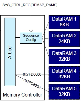
Figure 77 Memory blocks
The Sequence Configuration block controls the ordering of the first 3 memory cells according to the REMAP_RAMS value. Shuffling the memory cells allows the minimum number of RAM blocks to be retained to get the lowest power-down current consumption. The configuration setting dg_configSHUFFLING_MODE encodes the ordering of the first 3 RAM cells (RAM1, RAM2 and RAM3). The possible configurations are listed in Table 52.
| Value | Cell | Address | Size (kB) |
|---|---|---|---|
| 0x0 | DataRAM1 | 0x7FC0000 | 8 |
| DataRAM2 | 0x7FC2000 | 24 | |
| DataRAM3 | 0x7FC8000 | 32 | |
| 0x1 | DataRAM2 | 0x7FC0000 | 24 |
| DataRAM1 | 0x7FC6000 | 8 | |
| DataRAM3 | 0x7FC8000 | 32 | |
| 0x2 | DataRAM3 | 0x7FC0000 | 32 |
| DataRAM1 | 0x7FC8000 | 8 | |
| DataRAM2 | 0x7FCA000 | 24 | |
| 0x3 | DataRAM3 | 0x7FC0000 | 32 |
| DataRAM2 | 0x7FC8000 | 24 | |
| DataRAM1 | 0x7FCE000 | 8 |
For example, if 50 KB of RAM needs to be retained then the optimal
dg_configSHUFFLING_MODE value is 0x1. In this way, RAM5 cell
(mandatory, 32 KB) and RAM2 cell (mapped at 0x7fc0000 after shuffling,
24 KB) may be retained by setting the configuration macro
dg_configMEM_RETENTION_MODE to 0x1D, resulting in 56 KB of total
retained RAM.
For the DA1680/1-01, there are three different memory layouts depending on the build configuration. The following sections describe these memory layouts in detail.
In the linker scripts of the applications distributed with the SDK, there are typically two retained memory sections defined. The first section, RetRAM0, contains the BLE ROM variables and the exchange table used for the communication with the BLE core, any code that must be retained and the zero initialized and RW variables retained by the application. The other section, RetRAM1, may contain, apart from the IVT, large blocks of zero-initialized retained data, like OS or BLE heaps. Other allocations of which type of data is placed in each section are possible by modifying the linker script accordingly.
Note
Linker scripts are centralized and so there is not dedicated linker script per project. Centralized linker scripts are backwards compatible and can be overridden by a custom linker script if needed so. There are two flavors of linker scripts one for BLE and one for non-BLE projects. Centralized linker scripts are located in <sdk_root_folder>/sdk/bsp/ldscripts/.
17.3.1. Memory setups for QSPI Cached execution mode
The following sections describe various memory configurations for executing the application code from the QSPI flash memory. In these memory setups, the application code located in the QSPI Flash memory is executed in place and the Cache memory is enabled.
The presented projects are BLE and non-BLE and they are split into two categories:
- non-optimized (all RAM cells are retained)
- optimized for low power consumption (some RAM cells are retained)
17.3.1.1. DA14680/681 – QSPI Cached BLE non-optimized project
In Figure 78, an example memory layout is given. Here the non-optimized BLE project is executed in QSPI cached mode. In this example, RetRAM0 uses RAM cells 4 (32 KB) and 5 (32 KB). In this setup, the overall retained memory is 128 KB (all RAM cells are retained).
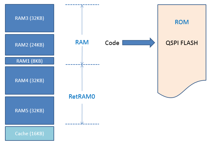
Figure 78 DA14680/681 – QSPI Cached BLE non-optimized project
Note
The BLE ROM variables start at 0x07FDC000 address.
17.3.1.2. DA14680/681 – QSPI Cached BLE optimized project
In Figure 79, an example memory layout is given. Here the optimized BLE project is executed in QSPI cached mode. In this example, RetRAM0 uses RAM4 and RAM5 cells (64 KB) while RetRAM1 uses RAM1 and RAM2 cells (32 KB). In this setup, the overall retained memory is 96 KB.

Figure 79 DA14680/681 – QSPI Cached BLE optimized project
Retention RAM optimization settings
The following defines must be added in the config/custom_config_qspi.h file of the application to enable RAM optimization.
#define dg_configOPTIMAL_RETRAM (1)
#define dg_configMEM_RETENTION_MODE (0x1B)
#define dg_configSHUFFLING_MODE (0x0)
An example taken from pxp_reporter demo application is shown in Code 40.
#define dg_configOPTIMAL_RETRAM                 (1)

#if (dg_configOPTIMAL_RETRAM == 1)
         #if (dg_configBLACK_ORCA_IC_REV == BLACK_ORCA_IC_REV_A)
                  #define dg_configMEM_RETENTION_MODE             (0x1B)
                  #define dg_configSHUFFLING_MODE                 (0x0)
         #else
                  #define dg_configMEM_RETENTION_MODE             (0x07)
                  #define dg_configSHUFFLING_MODE                 (0x0)
         #endif
#endif
Note
BLE ROM variables start at 0x07FDC000 address.
17.3.1.3. DA14680/681 – QSPI non-BLE non-optimized project
In Figure 80, an example memory layout is given. Here the non-optimized non-BLE project is executed in QSPI cached mode. In this example, RetRAM0 uses RAM cells 4 (32 KB) and 5 (32 KB). In this setup, the overall retained memory is 128 KB (all RAM cells are retained).
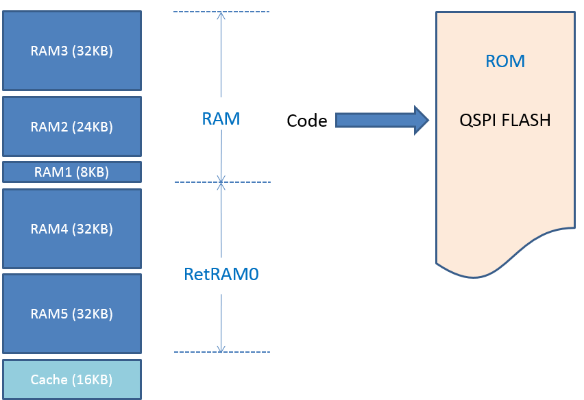
Figure 80 DA14680/681 – QSPI non-BLE non-optimized project
17.3.1.4. DA14680/681 – QSPI non-BLE optimized project
In Figure 81, an example memory layout is given. Here the optimized non-BLE project is executed in QSPI cached mode. In this example, RetRAM0 uses only RAM cell 2 (24 KB). In this setup, the overall retained memory is 24 KB.
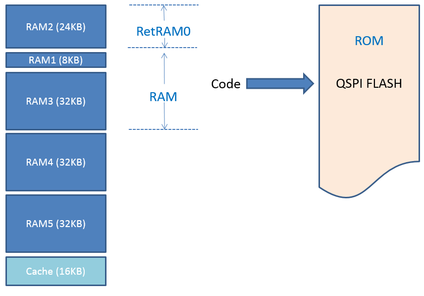
Figure 81 DA14680/681 – QSPI non-BLE optimized project
Retention RAM optimization settings
The following defines must be added in the config/custom_config_qspi.h file of the application to enable RAM optimization.
#define dg_configOPTIMAL_RETRAM (1)
#define dg_configMEM_RETENTION_MODE (0x02)
#define dg_configSHUFFLING_MODE (0x1)
17.3.1.5. DA14682/683, DA15100/1 – QSPI Cached BLE non-optimized project
In Figure 82, an example memory layout is given. Here the non-optimized BLE project is executed in QSPI cached mode. In this example, RetRAM0 uses RAM cells 3 (32 KB), 2 (24 KB) and 1 (8 KB). In this setup, the overall retained memory is 128 KB.
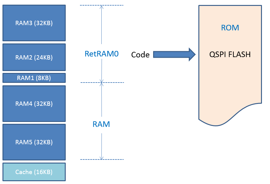
Figure 82 DA14682/683, DA15100/1 – QSPI Cached BLE non-optimized project
Note
BLE ROM variables start at 0x07FC0200 address.
17.3.1.6. DA14682/683, DA15100/1 Cached BLE optimized project
In Figure 83, an example memory layout is given. Here the optimized BLE project is executed in QSPI cached mode. In this example, RetRAM0 uses RAM cells 1 (8 KB), 2 (24 KB) and 3 (32 KB). In this setup, the overall retained memory is 64 KB.
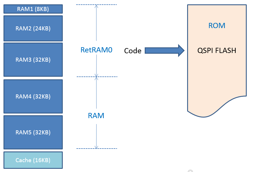
Figure 83 DA14682/683, DA15100/1 – QSPI Cached BLE optimized project
Retention RAM optimization settings
The following defines must be added in the config/custom_config_qspi.h file of the application to enable RAM optimization.
#define dg_configOPTIMAL_RETRAM (1)
#define dg_configMEM_RETENTION_MODE (0x07)
#define dg_configSHUFFLING_MODE (0x0)
Note
BLE ROM variables start at 0x07FC0200 address.
17.3.1.7. DA14682/683, DA15100/1 – QSPI Cached non-BLE non-optimized project
In Figure 84, an example memory layout is given. Here the optimized BLE project is executed in QSPI cached mode. In this example, RetRAM0 uses RAM cells 1 (8 KB), 2 (24 KB) and 3 (32 KB). In this setup, the overall retained memory is 64 KB.
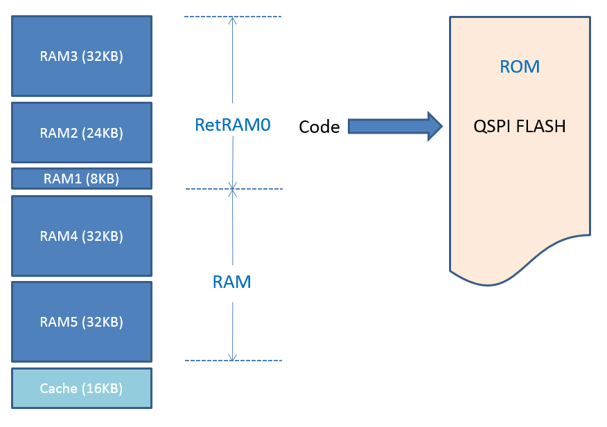
Figure 84 DA14682/683, DA15100/1 – QSPI Cached non-BLE non-optimized project
17.3.1.8. DA14682/683, DA15100/1 – QSPI non-BLE optimized project
In Figure 85, an example memory layout is given. Here the optimized non-BLE project is executed in QSPI cached mode. In this example, RetRAM0 uses only RAM cell 2 (24 KB). In this setup, the overall retained memory is 24 KB (all RAM cells are retained).

Figure 85 DA14682/683, DA15100/1 – QSPI non-BLE optimized project
Retention RAM optimization settings
The following defines must be added in the config/custom_config_qspi.h file of the application to enable RAM optimization.
#define dg_configOPTIMAL_RETRAM (1)
#define dg_configMEM_RETENTION_MODE (0x02)
#define dg_configSHUFFLING_MODE (0x1)
17.3.2. Memory setups for RAM execution mode
This section describes several configurations that allow executing the application code from RAM memory (although defined as ROM in linker). In these memory configurations the application code located in the defined as ROM retained RAM memory cells, is executed in place. The Cache memory is enabled.
- non-optimized (all RAM cells are retained)
- optimized for low power consumption (some RAM cells are retained)
17.3.2.1. DA14680/681 – RAM BLE non-optimized project
In Figure 86, an example memory layout is given. Here the non-optimized BLE project is executed in RAM execution mode. In this example the ROM memory has 64 KB size and uses RAM cells 1 (8 KB), 2 (24 KB) and 3 (32 KB). RetRAM0 uses RAM cell 4 (32 KB) and 5 (32 KB). In this setup, the overall retained memory is 128 KB (all RAM cells are retained).
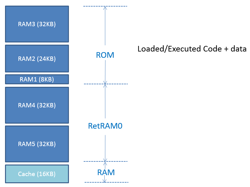
Figure 86 DA14680/681 – RAM BLE non-optimized project
Note
BLE ROM variables start at 0x07FDC000 address.
17.3.2.2. DA14680/681 – RAM non-BLE non-optimized project
In Figure 87, an example memory layout is given. Here the non-optimized non-BLE project is executed in RAM execution mode. In this example the ROM memory has 64 KB size and uses RAM cells 1 (8 KB), 2 (24 KB) and 3 (32 KB). RetRAM0 uses RAM cell 4 (32 KB) and 5 (32 KB). In this setup, the overall retained memory is 128 KB (all RAM cells are retained).
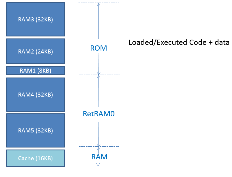
Figure 87 DA14680/681 – RAM non-BLE non-optimized project
17.3.2.3. DA14682/683, DA15100/1 – RAM BLE non-optimized project
In Figure 88, an example memory layout is given. Here the non-optimized BLE project is executed in RAM execution mode. In this example the ROM memory has 128 KB size. RetRAM0 uses RAM cell 3 (32 KB. In this setup, the overall retained memory is 128 KB (all RAM cells are retained).
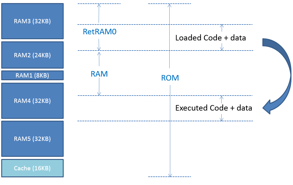
Figure 88 DA14682/683, DA15100/1 – RAM BLE non-optimized project
Note
BLE ROM variables start at 0x07FC0200 address.
17.3.2.4. DA14682/683, DA15100/1 – RAM non-BLE non-optimized project
In Figure 89, an example memory layout is given. Here the non-optimized BLE project is executed in RAM execution mode. In this example the ROM memory has 128 KB size. RetRAM0 uses RAM cell 3 (32 KB. In this setup, the overall retained memory is 128 KB (all RAM cells are retained).
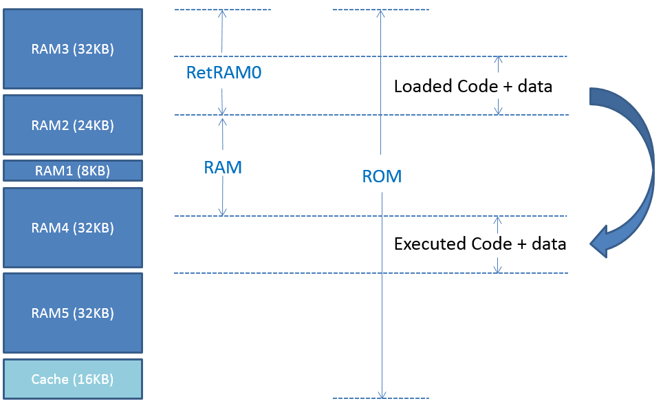
Figure 89 DA14682/683, DA15100/1 – RAM non-BLE non-optimized project
17.3.3. Memory setup for the OTP Cached execution mode (DA14680/1-01)
The only difference with the QSPI cached mode is that the code resides in the OTP instead of the QSPI Flash. Due to the limited size of the OTP, the maximum size of the application image is 58 KB. Figure 90 depicts the memory setup for an OTP cached application with image size 58 KB, retaining 64 KB of RAM during sleep (cells 1, 2 and 5).
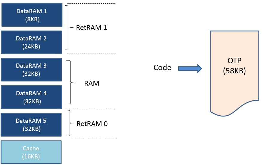
Figure 90 Memory setup for the OTP Cached execution mode (DA14680/1-01)
17.3.4. Memory setup for the OTP Mirrored execution mode (DA14680/1-01)
Note
The SDK has been developed to support only cached mode from Flash. This section is provided only as reference.
In mirrored mode, the application code is copied into RAM before it is executed. There are two available memory setups for the OTP Mirrored execution mode. The main difference is whether 1 or 2 sections will be used for non-retained data. In both configurations Cache memory is off and so may be used by the application. There is no RetRAM1 section since all memory is retained in this mode. The application code has to be retained during sleep as there is no mechanism to restore it at wake-up. Due to this requirement, RAM cell shuffling is irrelevant while the value of the dg_configMEM_RETENTION_MODE must be 0x1F.
In the first configuration, the RAM section of the linker script (normally non-retained data) is placed in the RAM cell of Cache. The ECC buffer cannot be placed in this region. This setup is shown in Figure 91.
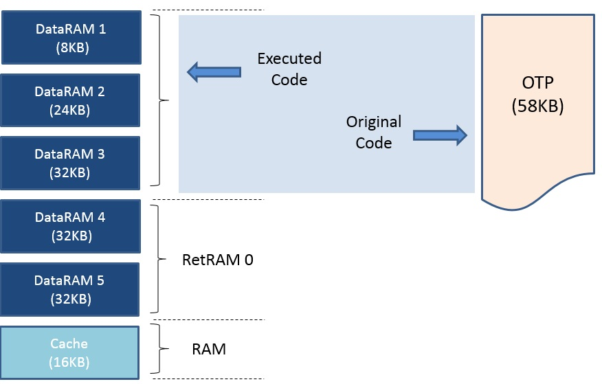
Figure 91 Setup 1 for the OTP Mirrored execution mode (DA14680/1-01)
In the second configuration, the linker script has two RAM sections. The first one (RAM1) is placed in the RAM cell of the Cache as in the first configuration. Here there is also space after the end of the application image in RAM and the beginning of RetRAM0 section which can also be used for data (RAM2). Note that the ECC buffer can be placed in RAM2. This configuration is shown in Figure 92.
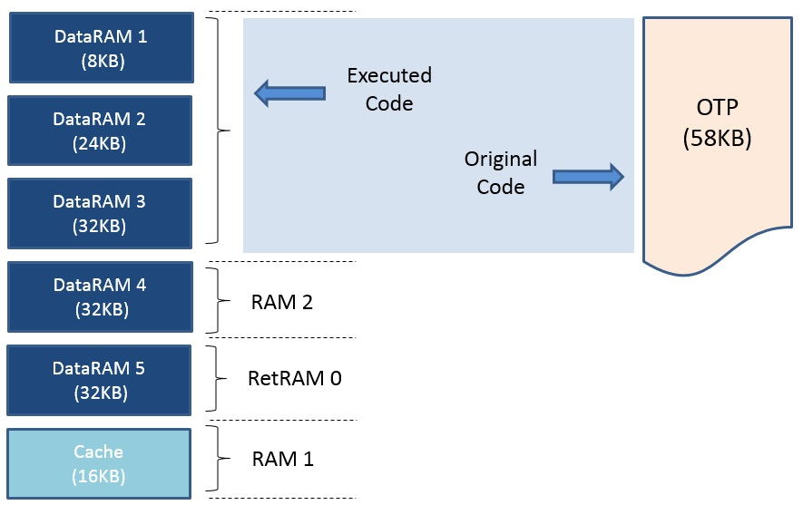
Figure 92 Setup 2 for the OTP Mirrored execution mode (DA14680/1-01)