16. Drivers and Adapters
16.1. Introduction
The DA1468x family of devices supports several peripherals on different interfaces. To support them the SmartSnippets™ DA1468x SDK provides Low Level Drivers (LLD) and/or Adapters for each of the available hardware peripherals.
A LLD provides a simple API to use the peripheral and abstract the complexities of using the peripheral registers directly.
An Adapter provides a higher level service allowing different tasks to safely share the peripheral and also integrate with the CPM to manage power-down modes.
The rest of this Section will provide an overview of the available Drivers and Adapters.
Warning
All drivers and adapters in the SmartSnippets™ DA1468x SDK are supplied in full source to aid debugging. However, modifying the drivers is not advised.
16.2. Drivers
This section will cover the LLDs for the peripherals of the DA1468x. The LLDs allow application software code to access and use the device peripherals without detailed knowledge of the hardware implementation, such as bits and their position within hardware registers.
It is recommended to only use the LLD drivers to access the device peripherals as the LLDs are tested and verified. Direct access to hardware resources (e.g. registers or peripheral interfaces) might lead to conflicts with lower level FW functions accessing the same resources through LLDs and lead to system instabilities. For each hardware peripheral a dedicated header file describes the API functions of the peripheral, lists capabilities and defines control structures which are needed to interact with its particular LLD. The header files can be found under <sdk_root_directory>/sdk/bsp/peripherals/include. Table 46 lists all available LLDs.
| Filename | Description |
|---|---|
| hw_aes_hash.h | Definition of API for the AES/HASH Engine Low Level Driver. |
| hw_breath.h | Definition of API for the Breath timer Low Level Driver. |
| hw_cpm.h | Clock and Power Manager header file. |
| hw_crypto.h | Interrupt handling for the crypto engines (AES/HASH, ECC) |
| hw_dma.h | Definition of API for the DMA Low Level Driver. |
| hw_ecc.h | Definition of API for the ECC Engine Low Level Driver. |
| hw_ecc_curves.h | ECC Engine curves parameters. |
| hw_ecc_ucode.h | ECC Engine microcode. |
| hw_fem_sky66112-11.h | FEM Driver for SKYWORKS SKY66112-11 Low Level Driver API. |
| hw_gpadc.h | Definition of API for the GPADC Low Level Driver. |
| hw_gpio.h | Definition of API for the GPIO Low Level Driver. |
| hw_hard_fault.h | Hard-Fault Handler. |
| hw_i2c.h | Definition of API for the I2C Low Level Driver. |
| hw_irgen.h | Definition of API for the IR generator Low Level Driver. |
| hw_keyboard_scanner.h | Definition of API for the Keyboard scanner Low Level Driver. |
| hw_led.h | Definition of API for the LED Low Level Driver. |
| hw_otpc.h | Definition of API for the OTP Controller driver. |
| hw_qspi.h | Definition of API for the QSPI Low Level Driver. |
| hw_quad.h | Definition of API for the QUAD Decoder Low Level Driver. |
| hw_rf.h | Radio module (RF) Low Level Driver API. |
| hw_soc.h | Definition of API for the SOC Low Level Driver. |
| hw_spi.h | Definition of API for the SPI Low Level Driver. |
| hw_tempsens.h | Implementation of the Hardware Temperature Sensor interface abstraction layer. |
| hw_timer0.h | Definition of API for the Timer0 Low Level Driver. |
| hw_timer1.h | Definition of API for the Timer1 Low Level Driver. |
| hw_timer2.h | Definition of API for the Timer2 Low Level Driver. |
| hw_trng.h | Definition of API for the True Random Number Generator Low Level Driver. |
| hw_uart.h | Definition of API for the UART Low Level Driver. |
| hw_usb.h | Header for low level DA1680 USB drive |
| hw_usb_ch9.h | Header file with USB configuration info for DA1680 USB driver. |
| hw_usb_charger.h | Definition of API for the USB Charger. |
| hw_watchdog.h | Definition of API for the Watchdog timer Low Level Driver. |
| hw_wkup.h | Definition of API for the Wakeup timer Low Level Driver. |
| sys_tcs.h | TCS Handler header file. |
In addition to the LLDs listed above, there is also a Low Level Pulse Density Modulation (PDM) Audio Interface driver. The PDM audio interface driver uses the Audio Processing Unit (APU) and the Sample Rate Converter (SRC) devices to implement a PDM interface with input and output support. The driver supports input and output directly from/to an application using the SRC I/O registers at various sample rates. It also supports both master and slave PDM mode. The Low Level Interface driver file can be found under <sdk_root_directory>/sdk/interfaces/audio/include/if_pdm.h.
16.2.1. LLD header Example
The table included below shows the typedefs, the enumerations and the functions for the quadrature decoder hardware as an example.
Note
All API calls starting with hw_xx indicate an LLD function.
| Typedefs | |
|---|---|
| typedef void | (*hw_quad_handler_cb) (void) |
| QUAD interrupt callback. | |
| Enumerations | |
| typedef enum | {HW_QUAD_CHANNEL_NONE = 0, HW_QUAD_CHANNEL_X = (1 << 0),
HW_QUAD_CHANNEL_Y = (1 << 1),
HW_QUAD_CHANNEL_Z = (1 << 2),
HW_QUAD_CHANNEL_XY = HW_QUAD_CHANNEL_X | HW_QUAD_CHANNEL_Y,
HW_QUAD_CHANNEL_XZ = HW_QUAD_CHANNEL_X | HW_QUAD_CHANNEL_Z,
HW_QUAD_CHANNEL_YZ = HW_QUAD_CHANNEL_Y | HW_QUAD_CHANNEL_Z,
HW_QUAD_CHANNEL_XYZ = HW_QUAD_CHANNEL_X | HW_QUAD_CHANNEL_Y | HW_QUAD_CHANNEL_Z,
HW_QUAD_CHANNEL_ALL = HW_QUAD_CHANNEL_XYZ
} HW_QUAD_CHANNEL;
|
| Channels definitions. | |
| Functions | |
| static inline void | hw_quad_init(uint16_t clk_div) |
| Initialization of QUAD driver | |
| static inline void | hw_quad_enable(void) |
| Enable QUAD driver | |
| static inline void | hw_quad_disable(void) |
| Disable QUAD driver. | |
| static inline void | hw_quad_set_channels(HW_QUAD_CHANNEL ch_mask) |
| Set channels state | |
| static inline void | hw_quad_enable_channels(uint8_t ch_mask) |
| Enable channels | |
| static inline void | hw_quad_disable_channels(uint8_t ch_mask) |
| Disable channels | |
| static inline HW_QUAD_CHANNEL | hw_quad_get_channels(void) |
| Get channels state | |
| Void | hw_quad_register_interrupt(hw_quad_handler_cb handler, uint16_t tnum); |
| Turn on QUAD interrupt | |
| static inline bool | hw_quad_is_irq_gen(void) |
| Check if interrupt has occurred | |
| Void | hw_quad_unregister_interrupt (void) |
| Turn off QUAD interrupt | |
| static inline int16_t | hw_quad_get_x(void) |
| Get the number of steps from X channel | |
| static inline int16_t | hw_quad_get_y(void) |
| Get the number of steps from Y channel | |
| static inline int16_t | hw_quad_get_z(void) |
| Get the number of steps from Z channel | |
16.2.2. Documentation
All LLD header files contain the description of the individual API methods, any types they define and their input and output parameter as well as their output types. The LLD header files were written to support the documentation generation tool Doxygen (http://www.doxygen.org). This approach allows the generation of an HTML-like description of each of the individual LLD header files including all possible typedefs and defines as well as an accurate description of all API calls and their parameters. Additionally, it gives a short summary of what each one of the API calls does.
Please refer to [Ref_02] to find more details on how to generate an HTML description of a particular LLD. Figure 69 presents the main Doxygen page found at <sdk_root_directory>/doc/html/index.html.
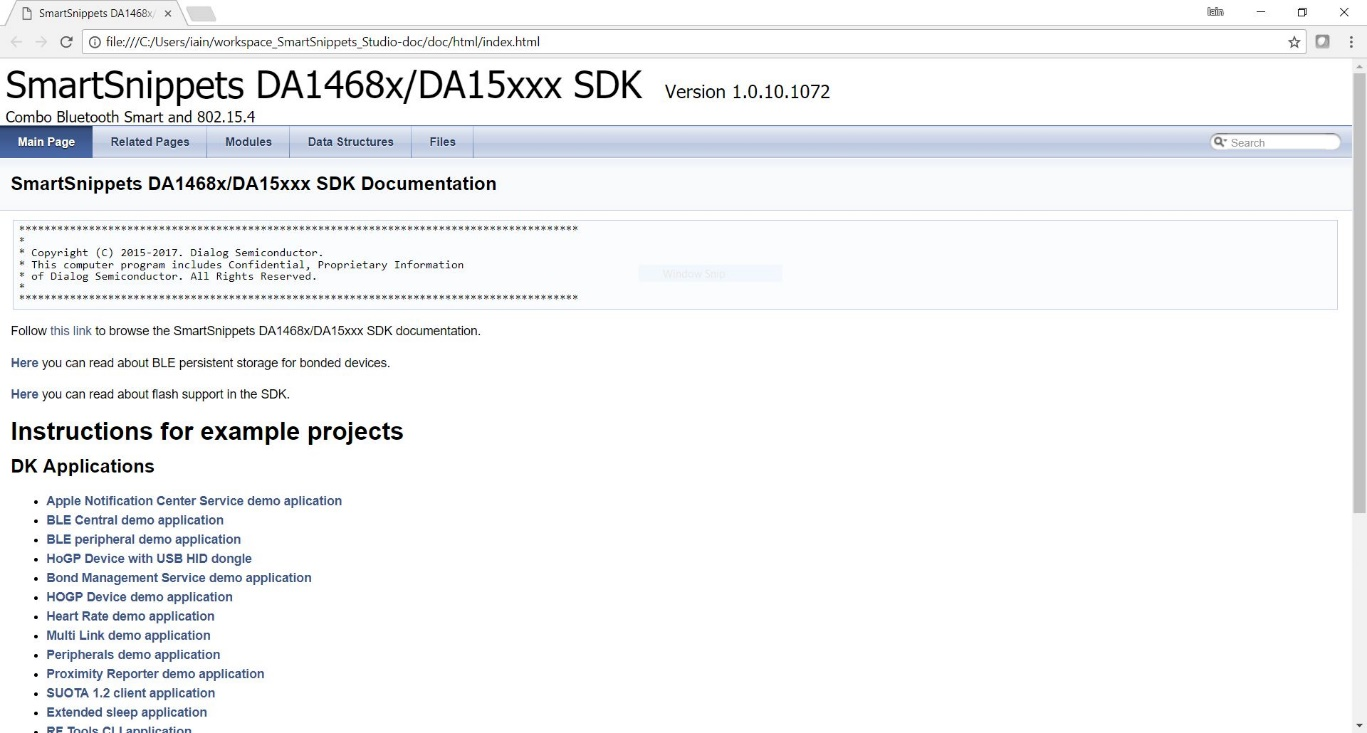
Figure 69 Html file generated by Doxygen
16.3. Adapters
Drivers may also contain a higher layer –the adapter- which allows more than one application thread to request access and get serviced by the driver. Please note that the same “adapter” scheme is used for data buffers, utilities and other system resources that could be utilized by an application as shown in Figure 70.
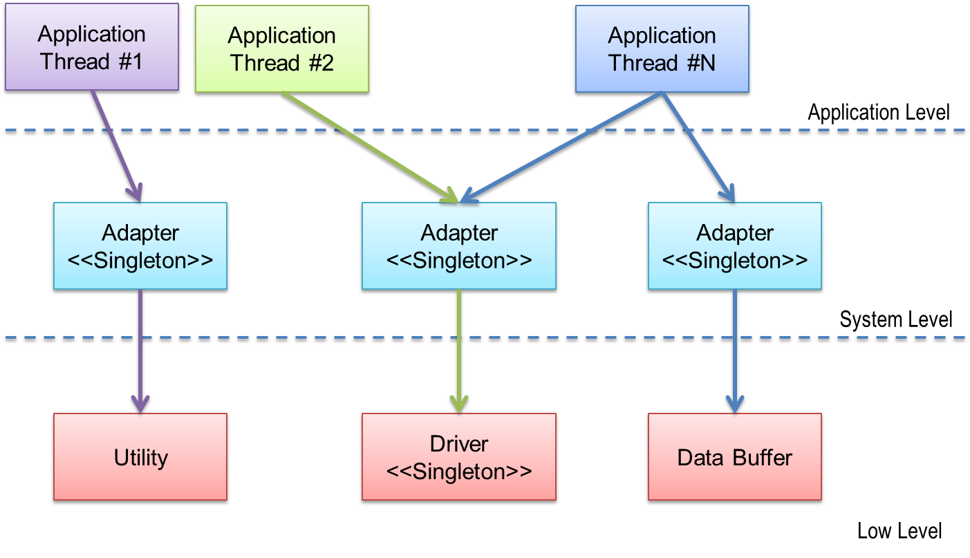
Figure 70 Adapter overview
The adapters as provided by the SmartSnippets™ SDK enables requests for a specific driver or resource from different tasks to be managed to handle resource availability.
The adapters use OS features such as semaphores or events and the resource management API in the osal layer to manage multiple simultaneous resource acquisition/release requests. The adapters not only provide access to the peripheral, but also make sure that other tasks which are currently accessing it, suspend their operation until the peripheral is once again released. They also interact with the CPM module so that device will only sleep if all peripherals are inactive.
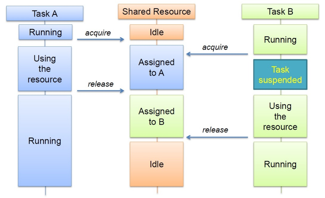
Figure 71 Adapter communication
Note
Adapters are not implemented as separate tasks and should be considered as an additional layer between the application and the LLD.
The recommendation is to use the adapters to access the hardware peripherals where possible.
The adapter header files can be found under <sdk_root_directory>/sdk/bsp/adapters/include. Table 48 lists all
available adapters.
| Filename | Description |
|---|---|
| ad_battery.h | Battery adapter API. |
| ad_crypto.h | ECC and AES/HASH device access API |
| ad_defs.h | Common definitions for adapters. |
| ad_flash.h | Flash adapter. |
| ad_gpadc.h | GPADC adapter API. |
| ad_i2c.h | I2C device access API. |
| ad_keyboard_scanner.h | Keyboard Scanner Adapter API |
| ad_spi.h | SPI adapter API. |
| ad_uart.h | UART adapter API. |
| ad_nvms.h | Nonvolatile memory storage API. |
| ad_nvparam.h | NV Parameters adapter interface. |
| ad_nvparam_defs.h | Define NV Parameters adapter interface. |
| ad_nvms_direct.h | NVMS direct access driver. |
| ad_nvms_ves.h | NVMS VES driver. |
| ad_rf.h | Radio module access functions. |
| ad_temp_sens.h | Temperature Sensor adapter API. |
| flash_partitions.h | Default partition table. |
| partition_def | Partition table entry definition. |
| partirion_table.h | Partition table. |
| platform_devices.h | Configuration of devices connected to board. |
| platform_nvparam.h | Configuration of non-volatile parameters on platform. |
| platform_nvparam_values.h | Parameter value. |
The SDK includes a “Peripherals demo application” which provides an excellent example of how many of the adapters are used. Please refer to the related Doxygen documentation and source code.
16.3.1. The UART adapter example
The UART adapter is an intermediate layer between the UART LLD and a user application. It allows the user to utilize the UART interface in a simpler way than using the pure LLD functions.
Features:
- Synchronous writing/reading operations block the calling task while the operation is performed using sempahores rather than relying on a polling loop approach. This means that while the hardware is busy transferring data, the Operating System (OS) scheduler may select another task for execution, thus utilizing processor time more efficiently. After the transfer finishes the calling task is released and resumes execution.
- DMA channel resource management for shared usage among various peripherals (e.g. I2C, UART). Interconnected peripherals may use the same DMA channel if necessary. The adapter takes care of DMA channel resource management.
- Ensuring that only one device can use the UART after acquiring it.
- Putting code between
ad_uart_bus_acquire(dev)andad_uart_bus_release(dev)ensures that only this task can use the UART to communicate with devicedevwhich was previously opened withad_uart_open. During this period no other device or task can use the UART until thead_uart_bus_releasefunction is called by the owning task. - Unlike other serial adapters (I2C and SPI), the UART adapter additionally allows direction-specific resource management. This allows two tasks to access the “read” and the “write” resource simultaneously. Use
ad_uart_bus_acquire_exandad_uart_bus_release_exto acquire and release a direction specific resource respectively.
Using the UART Adapter
dg_configUART_ADAPTER and dg_configUSE_HW_UART definition
To enable the UART adapter, both
dg_configUART_ADAPTERanddg_configUSE_HW_UARTmacros must be defined and set to 1 in the project’sconfig/custom_config_qspi.hheader file:
#define dg_configUART_ADAPTER (1)

#define dg_configUSE_HW_UART (1)
From this point on, the overall adapter implementation with all its integrated functions becomes available.
- The
platform_devices.hheader andUART_BUS macro(s)
Before utilizing the UART adapter the necessary UART_BUS macro(s) must
be created using the following definition pattern:
UART_BUS(bus_id,              // valid values: UART1, UART2
         name,                // name of UART, e.g. COM1
         baud_rate,           // UART baud rate from enum HW_UART_BAUDRATE
         data_bits,           // value from enum HW_UART_DATABITS
         parity,              // value from enum HW_UART_PARITY
         stop,                // value from enum HW_UART_STOPBITS
         auto_flow_control,   // 1 if auto flow control should be used,
                                 0 otherwise
         dma_channel)         // DMA number for Rx channel, Tx will     have next number,
                              // pass -1 for no
Macro(s) should be placed in a platform_devices.h header file, which can be found and copied from <sdk_root_directory>/sdk/bsp/adapters/include to the user’s project /config directory. If a new platform_devices.h file is not included there, the application will inherit the default macro(s) definitions from the original platform_devices.h header file, located in the <sdk_root_directory>/sdk/bsp/adapters/include.
These macro(s) describe the parameters of each UART bus and devices connected to it, as shown in Code 25:
UART_BUS(UART1, SERIAL1, HW_UART_BAUDRATE_115200, HW_UART_DATABITS_8, HW_UART_PARITY_NONE,
      HW_UART_STOPBITS_1, 0, 0, HW_DMA_CHANNEL_1, HW_DMA_CHANNEL_0, 0, 0)
User code
- Open the UART device
The first step is to open the UART device, which was defined by the UART_BUS macro. Calling the function shown in Code 26 opens the device and returns a handle to the main flow for using it in other adapter functions as well.
uart_device ad_uart_open(const uart_device_id dev_id);
The initial function call configures the UART block. Subsquent calls from other tasks simply return the already existing handle to the initialized UART, together with the parameters related for each device ID. The dev_id parameter is a second parameter of UART_BUS, for instance, SERIAL1. The returned uart_device handler will then be used in all other adapter functions from now on such as ad_uart_bus_acquire (handler_devic) or ad_uart_write (handler_device).
- Acquire access to the UART bus
Before using the UART the application task must request access to it so that no other tasks can use it and potentially corrupt the data transmitted or received. The access is acquired by using the function presented in Code 27:
void ad_uart_bus_acquire(uart_device dev);
This function waits for the UART bus to become available and when it is available locks it down and so reserves it for the current task. The function can be called several times. However, it is essential that the number of ad_uart_bus_release() function calls used for releasing the UART bus matches the number of ad_uart_bus_acquire() calls. When using the ad_uart_bus_acquire() function, only one task has access to the bus and another task is able to use it only after the ad_uart_bus_release() function has been successfully called.
- Write/Read to/from the UART device
Write and read functions can be divided into two groups:
- Synchronous
void ad_uart_write(uart_device dev, const char *wbuf, size_t wlen);
The function shown in Code 28 is used for writing to the UART device in a synchronous manner.
int ad_uart_read(uart_device dev, char *rbuf, size_t rlen, OS_TICK_TIME timeout);
Similarly, the function presented in Code 29, is used for reading rlen
bytes from the UART device, in a synchronous manner as well.
These two functions block the UART bus, however they do not block the operating system. FreeRTOS initially waits for bus access, and then blocks the calling task until a transaction is completed. Once a Write/Read process is finished, the UART bus is free to make another Read/Write operation for the same device.
In synchronous mode the calling task is blocked for the duration of the read or write access but other tasks are not.
- Asynchronous
void ad_uart_write_async(uart_device dev, const char *wbuf, size_t wlen, ad_uart_user_cb cb, void *user_data);
The function presented in Code 30, works in an asynchronous manner for writing wlen bytes to the UART device. Once the data is written to the UART the callback function cb is called. After that the ad_uart_bus_release() function is called. It is essential that until the callback is received, the caller does not release the wbuf memory buffer.
void ad_uart_read_async(uart_device dev, char *rbuf, size_t rlen, ad_uart_user_cb cb, void *user_data);
The function presented in Code 31, is used for reading rlen bytes from the UART device. The function does not necessary wait for the read operation to finish and starts from gaining access to the UART bus by calling the ad_uart_bus_acquire() function. Once the read operation begins, the user must not release the rbuf memory buffer. After all data is received the ad_uart_bus_release() function is called just before the callback function cb is called. To abort an already initiated read operation it is necessary to call the ad_uart_abort_read_async() function.
In the asynchronous case the calling task is not blocked by the read or write operation. It can continue with other operations while waiting for callback function to signal the completion of the read or write. Only at this point can rbuf be read or wbuf be refilled.
- Release the UART bus.
The function presented in Code 32 should be used for releasing the UART bus:
void ad_uart_bus_release(uart_device dev);
The function decrements an already acquired counter for a specific dev device and as soon as an internal countdown reaches zero, the UART bus is released and can be used by other tasks.
- Closing the UART device.
After all user operations are done and the device is not needed anymore for additional tasks, it should be closed by using the function presented in Code 33.
void ad_uart_close(uart_device device);
Example of Synchronous access:
uart_device dev;
static char wbuf[5] = Test;
char rbuf[5];

dev = ad_uart_open(SERIAL1);                  /* Open selected device */
ad_uart_bus_acquire(dev);                     /* Acquire access to bus */
ad_uart_write(dev, wbuf, sizeof(wbuf));       /* Write synchronously some data to UART device */
ad_uart_read(dev, rbuf, sizeof(rbuf), 100);   /* Read synchronously the data from UART device */
ad_uart_bus_release(dev);                     /*Release the UART */
ad_uart_close(dev);                           /* Close selected device */
16.4. The NVMS Adapter
16.4.1. Overview
The SmartSnippets™ DA1468x SDK includes a Non-Volatile Memory Storage (NVMS) Adapter providing non-volatile memory storage access capabilities to the application (including cached mode). The Adapter provides two main functions:
Non-Volatile Memory Storage to external Flash devices over standard SPI and Quad SPI performing Write / Read / Erase operations
Virtual EEPROM (VES) emulation with the following functionalities
- Wear-levelling
- Garbage Collection
- Power failure protection
The VES partition should be used for data that is frequently written to flash. The wear levelling and garbage collection allow the driver to maximize the number of write cycles from software given the limitations of the number of erase & write cycles of the actual flash device.
An overview of NVMS Adapter is shown in Figure 72.
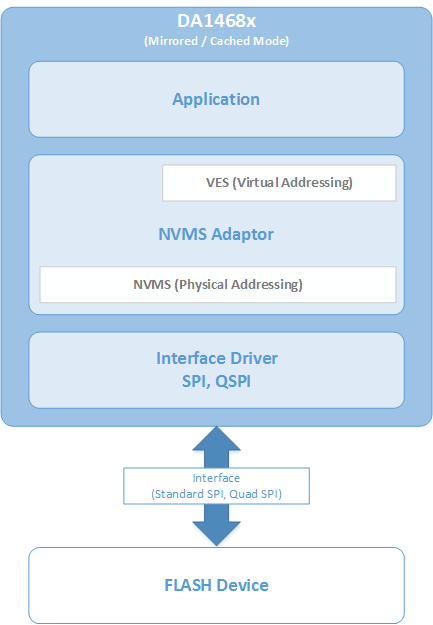
Figure 72 NVMS Overview
In theory NVMS is interface agnostic, as it is independent from the interface type being used (Standard SPI, I2C or QuadSPI) for data storage. However, the QSPI interface is a special interface from the NVMS perspective. As well as performing eXecution in Place (XiP), the QSPI Controller hardware block is also handling specific Flash-aware actions when Flash devices Read/Write/Erase operations are executed. As shown in Figure 74 when DA1468x is in cached mode, special mechanisms from the QSPI block are invoked.
The main consequence of this approach is that all Flash memory models used when utilizing NVMS over QSPI in cached mode must support Erase suspend/resume.
The rest of this section gives an overview on:
- Common NVMS interface for all usage scenarios
- Mechanisms implemented specifically for NVMS over QSPI in cached mode usage scenario
- Virtual EEPROM (VES) emulation
- Flash Memory Map in various usage scenarios.
16.4.2. Interface
NVMS Adapter exposes functions: ad_nvms_init(), ad_nvms_open(),
ad_nvms_write() and ad_nvms_read(), ad_nvms_erase(). Function
ad_nvms_init() must be called once at platform start to perform all
necessary initialization routines, including discovering underlying
storage partitions. The Application must open one of the partitions
before any read or write activity can be performed. . If several partitions are stored on one physical device (i.e. SPI Flash), opening one partition will limit read and writes to this partition only, making all addressing relative to beginning of that partition and not the whole flash. After opening, each partition is accessed in same way, but the exact way that data is stored depends on partition type. Only in the Virtual EEPROM (VES) partition do all reads and writes use virtual addresses that are independent of actual flash location.
nvms_t ad_nvms_open(nvms_partition_id_t id);

for (;;) {

   /* addr is any address in partition address space
    * buf can be any address in memory including QSPI mapped flash */

   ad_nvms_read(part, addr, buf, sizeof(buf));

   ad_nvms_write(part, addr, buf, sizeof(buf));

   }
Function ad_nvms_open() can be called many times since it does not
allocate any resources.
Function ad_nvms_read() can be called with any address within the
partition. If address is outside the partition boundaries
ad_nvms_read() will return 0. If the address is inside the partition
but the size would exceed the partition boundary only the data from
within the partition will be accessed.
Function ad_nvms_write() can be called with any address inside
partition address space.
How read or write actually work depends on the accessing method. In the current version of the platform, two accessing methods are supported: (a) Direct Access and (b) VES.
Direct Access
Direct access driver uses the relative address from the beginning of the partition but apart from this there is no address translation. Writes are performed exactly at requested addresses. If write would not change data (same data written) it will not be performed at all. If write can be performed without erasing it will be executed. If write can’t be performed without an erase, then the erase is also initiated. Currently the direct driver does not support caching so writing small pieces of data on an already used sector will trigger many erase operations. If a small write is required for some reason, then ad_nvms_erase() should be called explicitly before each write for efficiency reasons. Power failure during write or erase will result in data loss including data that was not touched by the last write. For power fail safe operation the VES partition should be used.
VES
For an application to use VES there are two prerequisites:
- The Partition ID should only be
NVMS_GENERIC_PART. dg_configNVMS_VESvariable should be defined.
VES driver provides access to the partition with power failure protection. It uses virtual addressing. The address space available for the user application is smaller than physical flash space occupied by the partition, but user can read and write to this address space without worrying that data will be lost. If power fails during a write, the specific data being written can be lost but other data will not be affected.
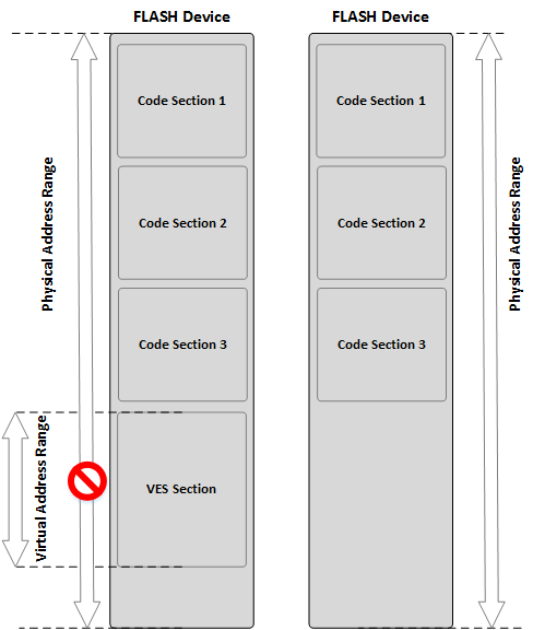
Figure 73 Virtual/Physical Addressing with and without VES
When VES is used:
- The application configures NVMS with the VES section information. The VES section is represented by a virtual address range that is mapped to a physical address range.
- NVMS prevents the application from performing “raw” writes to the allocated VES section
16.4.3. NVMS partition table
Code 36 shows the full list of the NVMS IDs and it can be found in
<sdk_root_directory>/sdk/bsp/adapters/include/partition_def.h
/**
* \brief NVMS Partition IDs
*/
typedef enum {
        NVMS_FIRMWARE_PART              = 1,
        NVMS_PARAM_PART                 = 2,
        NVMS_BIN_PART                   = 3,
        NVMS_LOG_PART                   = 4,
        NVMS_GENERIC_PART               = 5,
        NVMS_PLATFORM_PARAMS_PART       = 15,
        NVMS_PARTITION_TABLE            = 16,
        NVMS_FW_EXEC_PART               = 17,
        NVMS_FW_UPDATE_PART             = 18,
        NVMS_PRODUCT_HEADER_PART        = 19,
        NVMS_IMAGE_HEADER_PART          = 20,
} nvms_partition_id_t;
Code 37 shows the format for the data of the NVMS.
/**
 * \brief Partition entry.
 */
typedef struct partition_entry_t {
        uint8_t magic;          /**< Partition magic number 0xEA */
        uint8_t type;           /**< Partition ID */
        uint8_t valid;          /**< Valid marker 0xFF */
        uint8_t flags;          /**< */
        uint16_t start_sector;  /**< Partition start sector */
        uint16_t sector_count;  /**< Number of sectors in partition */
        uint8_t reserved2[8];   /**< Reserved for future use */
} partition_entry_t;
Table 49 describes each entry value.
Magic code (1 byte) |
Partition ID (1 byte) |
Valid flag (1 byte) |
Flags (1 byte) |
Start sector of partition (2 bytes) |
Sector count of partition (2 bytes) |
Reserve (8 bytes) |
|---|---|---|---|---|---|---|
| 0xEA. | From nvm_partition_id_t, 0xFF means it’s an invalid partition entry. |
0xFF means it’s a valid partition entry. | #define PARTITION_FLAG_READ_ONLY 1 #define RTITION_FLAG_VES 2 0 means it’s a normal writable/readable direct partition. 1 means it’s read only partition 2 means it’s a VES partition |
Start sector in flash of this partition. | Sector count of this partition. | For future use. |
16.4.4. NVMS over QSPI in cached mode
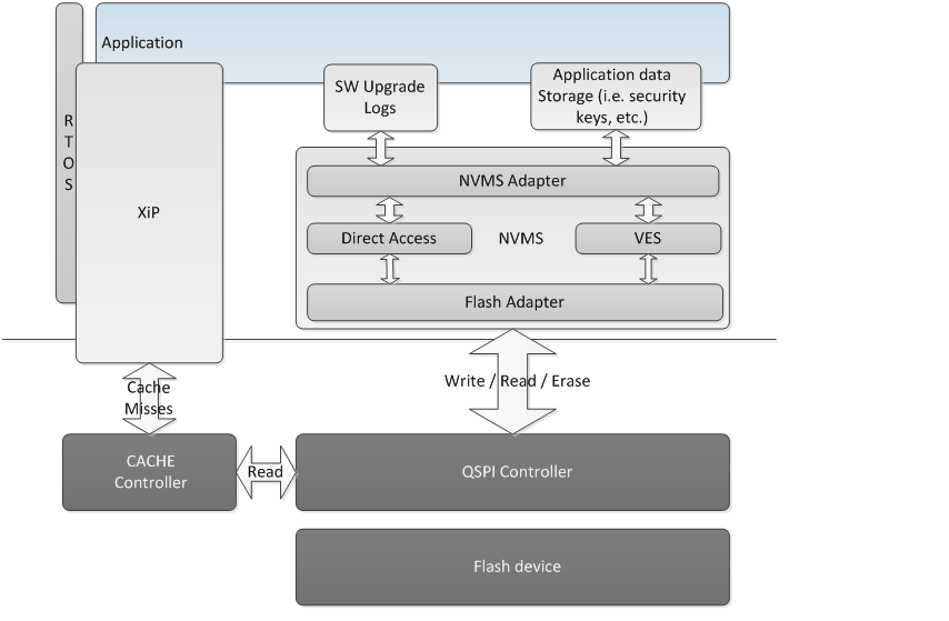
Figure 74 NVMS Adapter NVMS over QSPI and Virtual EEPROM emulation in Cached mode
When executing in place (XiP) from Flash in cached mode, the Flash device is used to store both firmware images and data.
Preemptive RTOS scheduling remains operational while programming the Flash.
PROGRAM and ERASE are the 2 critical Flash operations triggered by NVMS that need to be considered, as they can’t be performed at the same time as the READ operations triggered by the cache controller when it fetches cache lines from the FLASH to the cache RAM. To handle this conflict a specific mechanism is needed.
This mechanism is disabled when DA1468x is not in cached mode.
16.4.4.1. Slice PROGRAM operation
When writing a buffer to the Flash, the NVMS Adapter will slice the buffer into several smaller buffers and will issue several uninterruptible PROGRAM QSPI requests. Note that one parameter determining the size of the slice in bytes is stored in the flash itself. This parameter is determined by:
- The interrupt latency time in microseconds that the application authorizes.
- The flash model and the time taken to perform a program.
In general, the first byte to be programmed takes longer than the subsequent bytes so a trade-off is possible and the exact value is left to the application developer. However, a default value of 16 bytes is currently used.
16.4.4.2. Suspend/Resume ERASE Operation
Instead of slicing ERASE, the SmartSnippets™ DA1468x SDK leverages from Smartbond™ QSPI Controller SUSPEND/ERASE in auto-mode capability. It is assumed here that all selected Flash models support suspending ERASE.
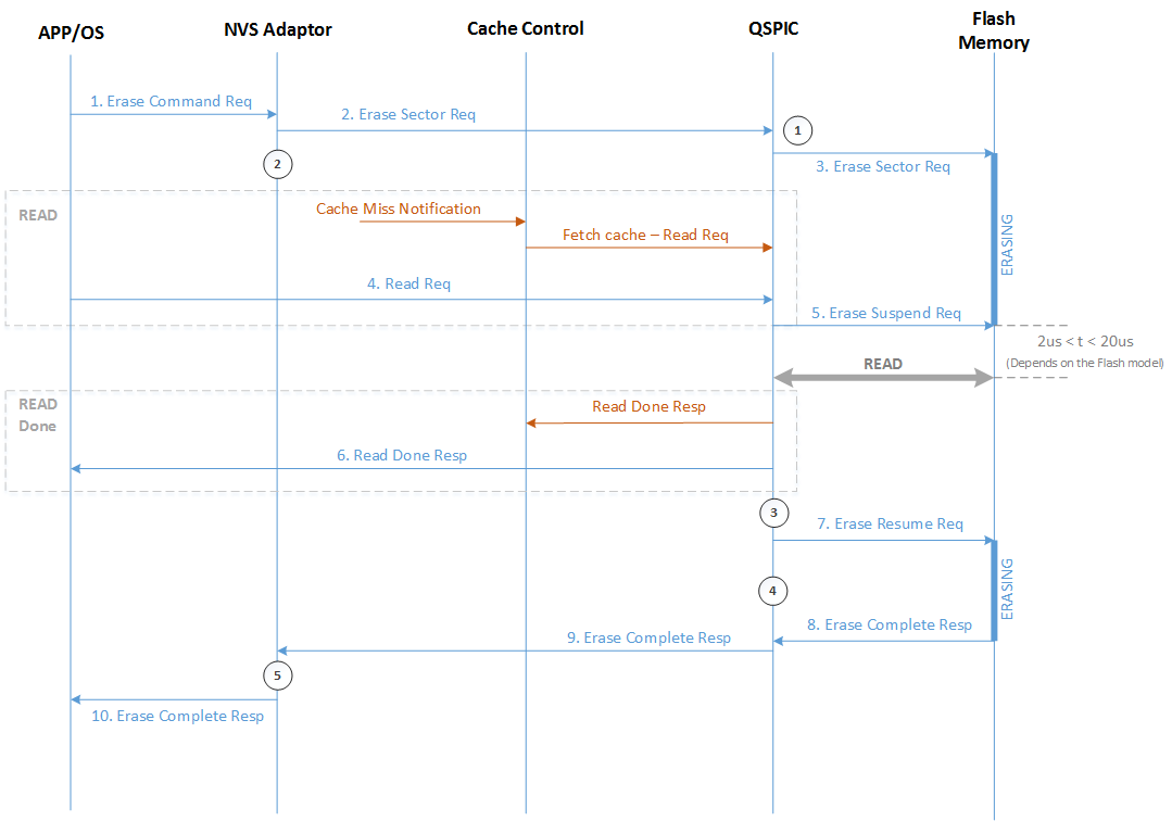
Figure 75 Suspend/Resume ERASE Operation
When requested to erase a sector by NVMS Adapter (staying in auto-mode), the QSPIC will automatically suspend the Erasing operation when a “read” from the Cache controller is triggered due to a miss hit. 2 parameters to be stored in the flash itself are SW configurable:
- ERASE/RESUME Hold: Refer to
QSPIC_ERASECMDB_REG[QSPIC_ERSRES_HLD] - RESUME/SUSPEND delay: Refer to
QSPIC_ERASECMDB_REG[QSPIC_RESSUS_DLY]
As QSPIC is not firing any interrupt on Erase completion, NVMS adapter
must poll QSPIC_ERASECTRL_CMD.
A detailed analysis of the Suspend/Resume ERASE Operation is shown in
Figure 75. The overall process begins when the Application/OS issues an
“Erase Command” Request. The NVMS Adapter receives the Request and
issues an “Erase Sector” Request to the QSPIC (Set QSPIC_ERASECTRL_REC [QSPIC_ERASE_EN]). This request changes the QSPIC state (Figure 75,
Reference Point 1), which checks whether the Flash Memory is idle for
a certain number of Clock Cycles before initiating the ERASE process
(QSPIC_ERASECMDB_REC [QSPIC_ERSRES_HLD]). Provided that the process
can be initiated, QSPIC issues an “Erase Sector” Request to the Flash
Memory and erasing begins. In the meantime, NVMS adapter also switches
state, by writing CHECK_ERASE_REG and ERASECTRL_REQ bits (Figure 75,
Reference Point 2). The Erase process taking place in the Flash Memory,
is able to be suspended by the QSPIC via an “Erase Suspend” Request
in two cases (i) if a Cache Miss Notification arrives in the Cache
control, leading to a “Fetch cache – Read” Request towards the QSPIC and
(ii) if a Read Request is issued by the Application/OS directly to the
QSPIC. The consequent “Erase Suspend” Request initiates the READ process
shown in Figure 75, where QSPIC reads data from the Flash Memory and
issues a “Read Done” Response to (i) Cache Control or (ii)
Application/OS respectively. Then, the QSPIC state switches again,
intending to resume Flash erase if memory is idle for a certain number
of Clock Cycles (QSPIC_ERASECMDB_REG [QSPIC_ERSRES_HLD]) as shown in
Figure 75, Reference Point 3. Provided that the Flash erase can be
resumed, QSPIC issues an “Erase Resume” Request towards the Flash Memory
and changes state once more. In its current state (Figure 75, Reference
Point 4) QPSIC is programmed to delay any new suspension of the
newly-resumed Erase for a pre-defined number of Clock Cycles
(QSPIC_ERASECMDB_REG [QSPIC_RESSUS_DLY]). In the meantime, Flash
Memory concludes the erasing process and notifies the QSPIC with an
“Erase Complete” Response. QSPIC then issues an “Erase Complete”
Response to the NVMS adapter, changing its state thus clearing
CHECK_ERASE_REG and ERASECTRL_REQ bits (Figure 75, Reference Point
5). Finally, NVMS Adapter issues the conclusive “Erase Complete”
Response to the Application/OS.
16.5. Logging
In the SDK the supported method of logging is to use the standard C API printf() in the application code. There are four mutually exclusive configuration options that will over-ride printf() in the file sdk/bsp/startup/config.c. These config options need to be set in config/custom_config_qspi.h
Warning
As printf takes a variable length list of arguments and supports many formatting options the execution time and memory usage are unbounded. This can easily break an embedded system.
The recommendation is to be very careful in using ``printf()``.
Ideally use printf() in application tasks as they are lowest priority and tend to have larger stacks.
If it needs to log inside a high priority RTOS task such as a timer callback then do not pass any variables to be parsed. Just print a short string with no formatting to avoid blowing the small 100 byte stack for the timer task and corrupting other variables.
The possible configuration options are:
CONFIG_RETARGETIn this mode the logging data is redirected to a UART with an over-ridden version of the low level
API _write(). The UART used is set using the further configuration option#define CONFIG_RETARGET_UART UART2In this case the function
periph_init()must enable the UART2 pins in the pin mux.hw_gpio_set_pin_function(HW_GPIO_PORT_1, HW_GPIO_PIN_3, HW_GPIO_MODE_OUTPUT, HW_GPIO_FUNC_UART2_TX);hw_gpio_set_pin_function(HW_GPIO_PORT_2, HW_GPIO_PIN_3, HW_GPIO_MODE_INPUT, HW_GPIO_FUNC_UART2_RX);With this configuration the
printf()statements appear on the host PC on the lower numbered COM port that is enumerated for the USB cable (COMx on Windows (both Pro DK and Basic DK)/dev/ttyUSB0for Pro DK and/dev/ttyACM0for Basic DK on Linux).dg_configSYSTEMVIEWIn this mode the logging data is redirected to SEGGER’s SystemView tool running on the Host PC. See 21 for instructions on setting up SystemView.
Note
SystemView only supports integer arguments (i.e. %d)
CONFIG_RTT
In this mode the logging data is redirected to a Segger Real Time Transfer (RTT) link which uses JTAG to communicate the data to the Segger RTT tools running on the Host PC.
CONFIG_NO_PRINT
In this mode nothing is logged and in fact the printf() function is overridden by an empty stub function.