13. System Management
The DA1468x has a number of independent power domains which are shown in Figure 33 that can be switched off to minimize power consumption.
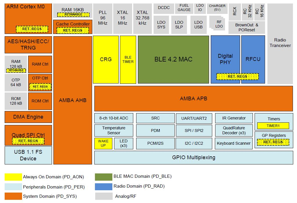
Figure 33 DA1468x Power Domains
The Clock and Power Manager (CPM) is responsible for managing these power domains, putting the system into sleep, handling the wake-up and providing the application tasks with a seamless way to control all system clocks. These are described in detail in the following sub-sections.
13.1. Power Modes
DA1468x supports the following power states (modes):
- Active,
- Idle,
- Extended sleep,
- Hibernation.
In Active mode, both System (PD_SYS) and Peripheral (PD_PER) power domains remain active. The BLE MAC (PD_BLE) and the Radio (PD_RAD) power domains may or may not remain active while the ARM Cortex M0 processor is able to execute code.
Idle mode is identical to Active mode, except that the ARM Cortex M0 core is executing a WFI() instruction which is just waiting for an interrupt to restart code execution. This interrupt may be an external one or simply the internal tick interrupt originating from the system’s clock. Idle mode offers significantly lower power consumption than the Active one.
When in Extended Sleep mode all power domains are powered down except for the Always-ON (PD_AON) domain. The PD_AON domain remains active to supply power to the blocks that can wake the system up, such as the BLE timer, the wake-up controller etc. The XTAL16M is stopped with only the low power clock remaining operational and the configured retained RAM blocks (Section 17.3) which retain data or in certain cases, code during extended sleep.
Hibernation mode bears two significant differences to Extended Sleep mode:
- Retained RAM is also powered down.
- The next wakeup event will internally generate a reset signal.
The first two modes, Active and Idle are categorized as power-up modes, during which the system is fully functional. The other two modes, Extended Sleep and Hibernation are categorized as power-down modes, during which the system is sleeping and thus consuming significantly less power.
13.2. Wake-up Process
13.2.1. Wake-up modes
Two wake-up modes are supported:
- Resume the OS without waiting for the
XTAL16Mto settle. This is the default setting. - Resume the OS only after the
XTAL16Mhas settled. This mode ensures that the application will run using the high-precision clock.
If any task that requires an accurate clock can be blocked until the XTAL16M clock becomes available, using the default setting is always recommended. Resuming the OS without waiting for the XTAL16M to settle ensures the lowest possible power consumption in typical applications. This is possible since there are tasks which only require RC16 to run and so they can finish earlier. This allows the system to return to Sleep mode with minimal delay.
13.2.2. Wake-up events
When in Sleep mode, DA1468x can wake-up in two ways:
- Synchronously, from the Timer1 or the BLE timer in Extended Sleep mode only.
- Asynchronously, from the Wake-up timer or the VBUS interrupt.
Certain applications require the system to exit Sleep mode to serve an OS Timer or a BLE event. If these are time-based events the low-power clock must be available during Sleep mode. Synchronous wake-up however is only supported in the Extended Sleep mode.
13.3. Sleep architecture
The Sleep architecture design is built around the following principles:
- The system must be able to wake up synchronously to serve OS and BLE events.
- The requirements of OS and BLE events may be different. Specifically, BLE events require the
XTAL16Mto have settled and be set as the system clock. On the other hand, an OS event may or may not have such requirement. For instance, an OS task that needs to read a value from a sensor via the I2C interface does not require theXTAL16Mclock. However, if the OS task uses the UART to read the sensor then theXTAL16Mis mandatory. - The system must be able to wake-up asynchronously.
- The process of switching between Sleep and Wake-up modes should be both simple and deterministic.
- The Clock and Power Manager (CPM) must control only the System and the Peripherals power domains. The BLE and the Radio power domains must be controlled independently by the BLE driver.
- No error will be introduced by the software architecture to the low
power clock other than that caused by the inherent physical
characteristics of the external crystal (in the case of
XTAL32K) or theRCX.
There are two sources that control the synchronous system wake-up, the OS and the BLE. The implementation should use a single timer to wake-up the system, regardless of which source it serves. This is to ensure that statements 4 and 6 of the previous list are covered. Since the BLE timer is not accessible when the BLE is powered-down, Timer1 becomes the only available option.
The implementation of Timer1 facilitates a system wake-up process with enough time for both BLE initiation and XTAL16M settling. When an XTAL 16RDY interrupt arrives, XTAL16M is set as the system clock and BLE wake-up takes place. Provided that the only task of BLE_LP_ISR is to power-up the BLE core, the necessary BLE_WAKEUP_LP interrupt is programmed to occur in a time window in which the BLE core should be already functional.
The CPM prevents the system entering Sleep mode when the BLE power domain is still active. Only after the BLE completes event handling and the existing BLE driver puts the BLE power domain into power down, will the CPM take over and put the whole system in Sleep mode. To ensure that the system will exit Sleep mode, the CPM calculates the next wake-up time. A certain time-frame which is defined as the maximum sleep time, may be applied prior to servicing the next synchronous event. To correctly program the sleep time, the CPM takes into account which OS or BLE event should be considered as the next wake-up source. XTAL16M settling time is not included in the calculation when an OS event wakeup is expected, only in the case of a BLE wakeup event. Possible overlaps of OS and BLE events are also taken into consideration.
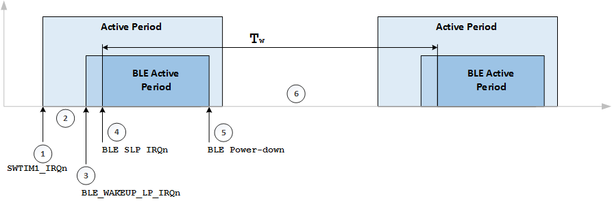
Figure 34 Synchronous BLE event
Figure 34 presents a typical scenario, where the system wakes-up for servicing a BLE event. The interrupts along with the system state each one triggers are clearly depicted:
- After
SWTIM1_IRQninterrupt, the system wakes-up and the clock isRC16. XTAL16Msettling time window. During this time, the system clock switches back toXTAL16M(or PLL) fromRC16.- Using a
BLE_WAKEUP_LP_IRQninterrupt, the BLE notifies the system that has woken-up and is now available. - The BLE core is active when a
BLE_SLP_IRQninterrupt occurs. - BLE goes to power-down after informing the CPM of the next wake-up time (
Tw). - Inactive Period.
The inactive period is calculated by the CPM based on the time that BLE is scheduled to wake-up. By the time the next BLE_WAKEUP_LP_IRQn arrives, the XTAL16M must have already settled and the clock switching from RC16 to XTAL16M must have been completed.
This scenario can be extended to include a wake-up from an asynchronous request, where the system is triggered by a request originated from the wake-up controller. In such case, the system is solely based on the RC16 clock, therefore doesn’t involve the XTAL16M. After the interrupt has been handled, the CPM puts the system back into Sleep mode by repeating the same process used in the synchronous case.
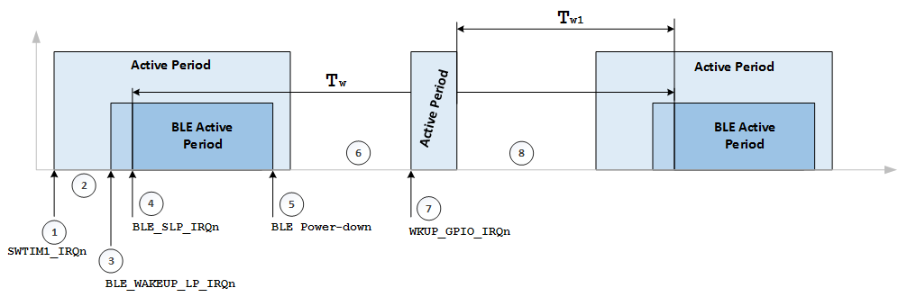
Figure 35 Asynchronous BLE event
Figure 35 presents the wake-up and sleeping process during an asynchronous event.
- After
SWTIM1_IRQninterrupt, the system wakes-up and the clock isRC16. XTAL16Msettling time window. During this time, the system clock switches back toXTAL16M(or PLL) fromRC16.- Using a
BLE_WAKEUP_LP_IRQninterrupt, the BLE notifies the system that has woken-up and is now available. - The BLE core is active when a
BLE_SLP_IRQninterrupt occurs. - BLE goes to power-down after informing the CPM of the next wake-up time (
Tw). - Inactive Period.
- A
WKUP_GPIO_IRQninterrupt is received by the system. During inactive period, the clock is set toRC16. - After serving the asynchronous request the CPM puts the system back to Sleep mode. However, the time to wake up is not Tw any more. The CPM must recalculate the time window based on the next scheduled event when BLE needs to be active. The new value is depicted as
Tw1in Figure 35.
To ensure correct operation it is necessary for the CPM to manage all the requirements of the various subsystems of DA1468x. The driver Adapters are designed to simplify the operation of the CPM in managing the sleep requirements of all the drivers in the system.
The Adapter for each driver implements a layer between the application and the low level hardware drivers. They control the tasks’ access to the resource so that multiple tasks can safely use the resource. The sharing of a resource between multiple tasks is illustrated Figure 71.
The Adapter is also responsible for handling the power management for the driver. It will initialize the hardware resource during wake-up and deal with the special case where the resource cannot be fully operational until the XTAL16M is available. In this case the Adapter can handle separately the partial initialization via the callback ad_wake_up_ind and the full initialization of the resource via the callback ad_xtal16m_ready_ind.
The Adapter(s) register to the CPM so that the CPM can inform them about the progress of wake-up or sleep entry. The API that is provided to the Adapters for this purpose is:
| API for the adapters | Description |
|---|---|
| pm_id_t pm_register_adapter(const adapter_call_backs_t *cb) | Registers an Adapter to the CPM. |
| void pm_unregister_adapter(pm_id_t id) | Unregisters an Adapter from the CPM. |
At registration, the Adapter provides its APIs for communication with the CPM. This API is listed in Table 28 and used by Adapters that are implemented as part of the SmartSnippetsTM DA1468x SDK.
| API for the communication with the CPM | Description |
|---|---|
| bool ad_prepare_for_sleep(void) | The CPM inquires the Adapter about whether the system can go to sleep. |
| void ad_sleep_canceled(void) | If an Adapter rejects sleep, the CPM calls this function to resume any Adapters that have previously accepted it. |
| void ad_wake_up_ind(bool) | The CPM informs the Adapter that the pad latches are to be removed so that it re-initializes the GPIOs that are used by the hardware resource it controls and, depending on the resource type, the resource itself. |
| void ad_xtal16m_ready_ind(void) | The CPM informs the Adapter that the XTAL16M is ready and is or may be set as the system clock. |
The Adapter also informs the CPM about the time it needs to prepare the hardware resource for power-down. The CPM uses this information when it executes the sleep entry procedure. This time will be zero in general but there are exceptions (e.g. the UART interface).
When the CPM is invoked to put the system to sleep (the OS is idle) and the BLE is powered-down, the CPM executes the following steps:
- Calculates the time when the OS needs to wake-up to serve its next scheduled event..
- Calculates the time when the BLE needs to wake-up to serve its next scheduled event.
- Determines the maximum sleep time that is allowed based on the results from Steps 1 and 2.
- If the calculated sleep time is larger than a pre-set minimum sleep time below which sleeping is not power efficient (
dg_configMIN_SLEEP_TIME), then the CPM informs all the registered Adapters about its intention to put the system in power-down by calling each Adapter’sad_prepare_for_sleep()function. The return value of this function allows the Adapters to tell the CPM that it cannot enter sleep as it still has work to do. - If all Adapters confirm the power-down entry, the CPM continues and puts the system into sleep.
- If at least one Adapter rejects the power-down entry, the CPM informs the Adapters that have already accepted it, to resume normal operation and puts the system into Idle mode.
During wake-up, CPM and Adapters interact twice:
First, when it prepares the system for power-up the CPM activates the Peripherals power-domain where it calls each Adapter’s ad_wake_up_ind() to inform them of the imminent removal of the pad latches.
Second, when the XTAL16RDY_IRQn ISR is called after the XTAL16M has settled it calls each Adapter’s ad_xtal16m_ready_ind() to inform them that the clock is ready.
Any Adapters such as the UART which need the high precision clock will perform the initialization of the resource at this point.
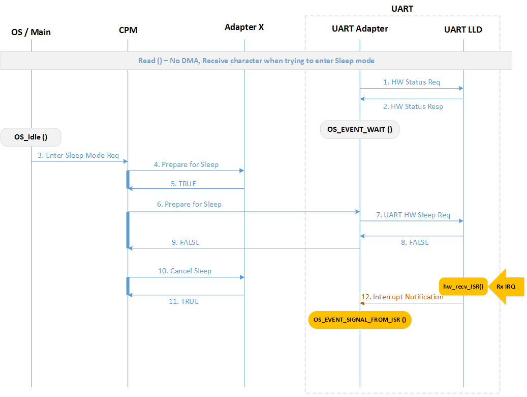
Figure 36 CPM and Adapter Interaction - an Adapter aborts sleep
The interaction between the CPM and the Adapters is shown in Figure 36. According to the scenario presented there, a system that consists of the OS, the CPM and two Adapters (Adapter X and UART Adapter) is about to switch mode, from Active to Sleep. The UART module includes two submodules, UART Adapter and UART LLD, which exchange hardware status messages [e.g. hw_uart_receive()] while waiting for an OS-originated event.
To enter power-down OS_Idle() issues a “Enter Sleep Mode Req” [pm_sleep_enter()] to the CPM. The CPM will first calculate sleep time and if sleep is possible will contact the first Adapter in the system, Adapter X, and send it a “Prepare for Sleep Req” [*ad_prepare_for_sleep()]. Adapter X accepts the power-down, starts preparing for it and responds by a simple “TRUE” response. Then the CPM calls the next Adapter in sequence, the UART. This adapter tries to deactivate the UART block unit, by notifying UART LLD via a “UART HW Sleep Req” [hw_uart_rx_off()]. However, during this process a character is received in the UART LLD, the Flow OFF check fails and the UART Adapter receives a “FALSE” notification which is forwarded to the CPM. After receiving the “FALSE” notification, CPM contacts Adapter X to inform that the system will remain in power-up state by sending a “Cancel Sleep” message [*ad_sleep_canceled()]. Finally, the system is placed in Idle state.
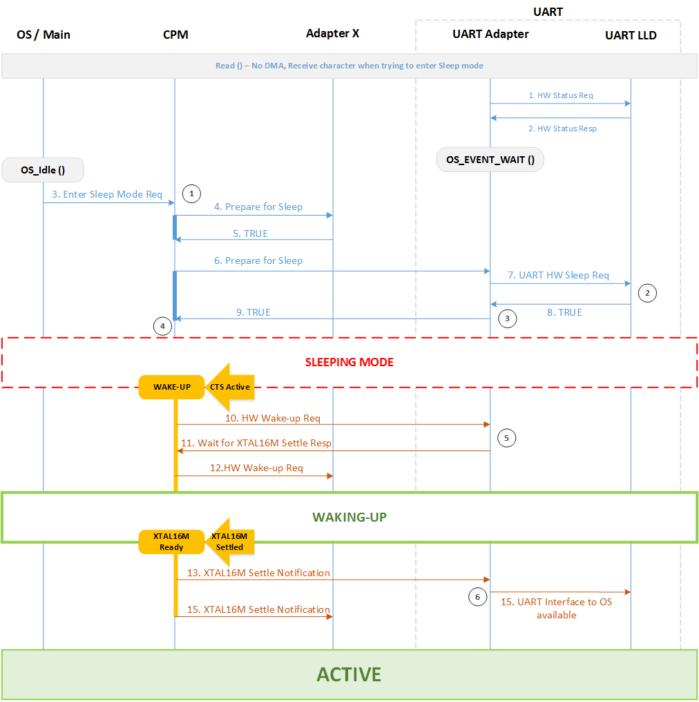
Figure 37 CPM and Adapter Interaction during Sleep/Active mode switch
Figure 37 illustrates the interaction of the CPM with the Adapters of the previous example (Figure 36), in a successful sleep entry and a subsequent wake-up from an external event (the CTS pin changes state). In this example, both Adapter X and the UART Adapter accept the power-down so the CPM puts the system into the proper power-down state. While sleeping, a transmit request from the remote host is issued and the system wakes-up. Before removing the pad latches, the CPM calls the ad_wakeup_ind() of both Adapters to perform partial or full initialization. The UART Adapter detects the remote host’s request and instructs the CPM not to put the system back to sleep until the XTAL16M has settled and the UART block is turned-on by calling the pm_defer_sleep_for(). This is the simpler approach as the CPM will immediately put the system to Idle state if there is nothing else to be done. If the call to pm_defer_sleep_for() is omitted then the system will be put into Idle state but following a more complex procedure. This procedure involves the CPM contacting the Adapters, the UART Adapter will deny the sleep request and the CPM will call the Idle WFI() after cancelling sleep for Adapter X. When the XTAL16M settles the CPM calls the ad_xtal16m_ready_ind() of both Adapters. The UART Adapter will check whether the system clock is the high precision clock and, if not, request it be changed. This is completed without delay. Then it can proceed with the initialization of the UART hardware.
13.3.1. BLE Wake-up
Special code is included in the SmartSnippets™ DA1468x SDK to ensure the proper wake-up of the BLE core. If a problem occurs, then an assertion is triggered. Two macros can be used to allow a percentage of such errors to occur without triggering an assertion: BLE_MAX_MISSES_ALLOWED and BLE_MAX_DELAYS_ALLOWED. Before explaining how these macros operate, a discussion about the BLE sleep and wake-up procedures is necessary.
During the BLE sleep preparation step the software calculates the time (time=``tS``) that the BLE core can be in sleep mode (or, in other words, the time when the BLE core must wake-up). The software then programs this time to the BLE core and instructs it to enter power-down state. Then the BLE core switches from the 16MHz clock to the low power clock and enters power-down state. While in this mode, the BLE power domain can be turned off to save power.
The wake-up sequence of the BLE core consist of the following steps (please refer also to the datasheet):
BLE_WAKEUP_LP_IRQoccurs at a predefined number of clocks (time =tW) before the time (time =tS) when the BLE core must wake-up. The term “wake-up” refers to the BLE core being powered up and running at 16MHz. So, the service routine of this interrupt is responsible for powering-up the BLE power domain and starting the fast clock before the time tS. It then waits for theBLE_SLP_IRQto occur to pass the execution to its handler.BLE_SLP_IRQoccurs at time tS or later. Ideally, if no delays have occurred thenBLE_SLP_IRQwill occur exactly attS. If, for any reason, the wake-up of the BLE core was delayed thenBLE_SLP_IRQ willoccur later thantS. WhenBLE_SLP_IRQoccurs the BLE core automatically switches from the low power clock to the 16MHz clock and enters power-up state. The ISR is responsible for performing clock compensation. This is readjusting the time counters of the BLE core (slot and uses timer) to take into account the sleep period (tS or a time period larger than tS).
The time tW is calculated to take account of potential normal delays in the system (i.e. a critical section that runs with the interrupts disabled) and make sure they do not affect the wake-up of the BLE core. So, by default, tW is larger than the “optimal” setting. Therefore, the service routine of the BLE_WAKEUP_LP_IRQ assumes that the wake-up of the BLE core will have been completed well before the BLE_SLP_IRQ is triggered. Based on this assumption, if the BLE_SLP_IRQ hits right after the wake-up of the BLE core, there is a high chance that the servicing of the BLE_WAKEUP_LP_IRQ has been delayed. This case is checked in the ble_lp_isr() when the code is built in DEVELOPMENT_MODE. Normally, an assertion would hit to indicate this “error”. However, the macro BLE_MAX_MISSES_ALLOWED can be used to allow for a small percentage of such delays. This can be used in applications where the maximum time that the system runs with the interrupts disabled, blocking the servicing of the BLE_WAKEUP_LP_IRQ, is larger than usual. The percentage is calculated as:
misses_allowed = (BLE_MAX_MISSES_ALLOWED /
BLE_WAKEUP_MONITOR_PERIOD) * 100%
After the BLE_WAKEUP_LP_IRQ ISR, the BLE_SLP_IRQ ISR executes. slp_isr() checks whether the BLE core was woken up in time or the wake-up was delayed. This is done by checking the programmed sleep time tS with the actual sleep time tA. If tA > tS then the wake-up was delayed by tA-tS low power clock cycles. This is as error as in most cases, it results in missing the BLE event that the system woke-up for. This case can happen if the interrupts were disabled for quite a long time. In that case, ble_wakeup_lp_isr interrupt would have been latched but its servicing would have been deferred until the interrupts were enabled. During this period, the BLE core would be sleeping. So, after powering the BLE core up, the BLE_SLP_IRQ would hit but the actual sleep time would have been larger than the programmed time. The macro BLE_MAX_DELAYS_ALLOWED can be used to allow for a small percentage of such delays in the same way as the macro BLE_MAX_MISSES_ALLOWED is used. The percentage is calculated as:
delays_allowed = (BLE_MAX_DELAYS_ALLOWED /
BLE_WAKEUP_MONITOR_PERIOD) * 100%
BLE_WAKEUP_MONITOR_PERIOD is set to 1024 by default.
13.4. Power configuration
The term “power configuration” iis used to denote the configuration of the system during sleep. In power-up modes, the system uses the DCDC converter as the main power supply (unless otherwise configured) as this setup offers lower power consumption.
Although the power setup is quite straightforward for the power-up modes, this is not the case for the power-down modes as there are various options for providing power to the power rails (see Figure 38). More specifically,
- The 3.3V output can be driven by the
LDO_ret(low power, low driving strength) or theLDO_VBAT_RET(high driving strength but resampling is required periodically to keep the correct voltage level, which increases power consumption). - The 1.8V output for the Flash can be provided by the LDO_IO_RET or
the DCDC. Note that the
LDO_IO_RETis powered from the 3.3V rail. Note that the DCDC requires periodic recharging to keep the outputs constant, which increases power consumption. - The 1.8V output for the external peripherals can be provided by the
LDO_IO_RET2or the DCDC. Note that theLDO_IO_RET2is also powered from the 3.3V rail. Note that the DCDC requires periodic recharging to keep the outputs constant, which increases power consumption. - The 1.4V output is not provided during sleep.
The low power clock is required to be active during sleep to be able to wake-up the part of the system that does the resampling of the bandgap or restoring the energy of the inductor of the DCDC.
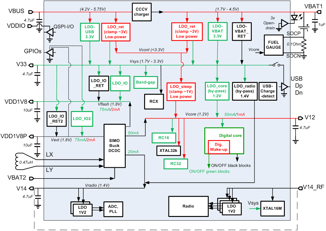
Figure 38 Power Management Unit
In Figure 38, the red color is used for the Sleep state and the green for the Active state.
13.4.1. Recommended Power Configuration
In recommended Power Configuration (sleep configuration) the 3.3V
rail is powered via the LDO_VBAT_RET. In this case it is required
to bring-up part of the system periodically in order to resample the
bandgap. The 1.8V for the Flash and for the external peripherals are
provided via the LDO_IO_RET and LDO_IO_RET2 respectively.
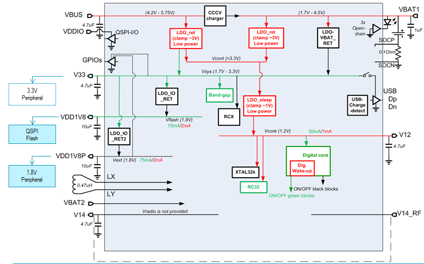
Figure 39 Recommended Power configuration
The SmartSnippets DA1468x SDK provides the following configuration settings:
| Available configuration settings | Description |
|---|---|
| dg_configSET_RECHARGE_PERIOD | This is the period of the Sleep Timer that is used to bring-up part of the system periodically to resample the bandgap voltage or to restore the energy of the inductor of the DCDC. |
| dg_configPOWER_FLASH | If set to ‘1’ then the 1.8V for the external QSPI Flash is supplied. |
| dg_configFLASH_POWER_DOWN | If set to ‘1’ then the QSPI Flash is put to “Power Down” for the duration of the sleep period. |
| dg_configFLASH_POWER_OFF | If set to ‘1’ then the QSPI Flash is powered-off during sleep (the 1.8V is turned-off during sleep). Note that dg_configFLASH_POWER_DOWN has priority over dg_configFLASH_POWER_OFF. If both are set, then the QSPI Flash will be put to “Power Down” mode while sleeping. |
| dg_configPOWER_EXT_1V8_PERIPHERALS | If set to ‘1’ then the 1.8V for the external peripherals is supplied. |
13.4.2. System Clock
The clock tree diagram of the DA1468x is depicted in Figure 40, a more detailed diagram is available in Appendix I.
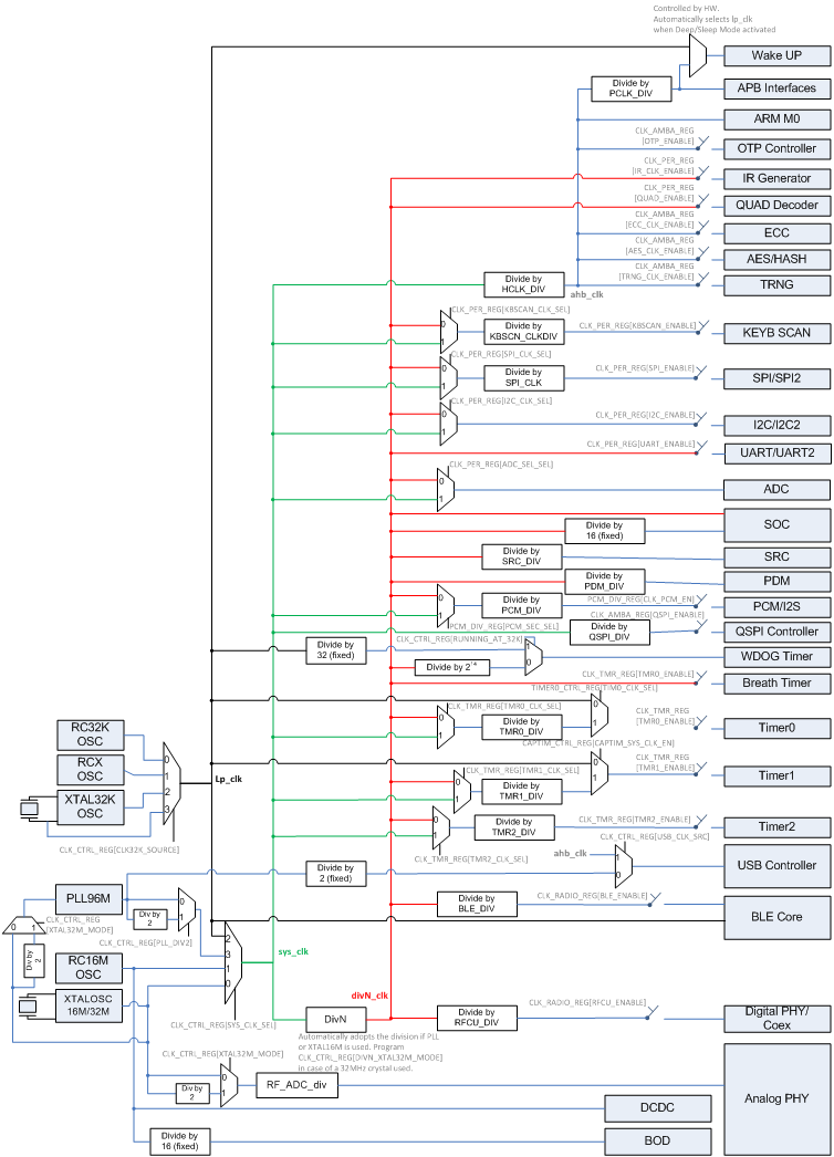
Figure 40 Clock tree diagram
The clock manager, which is part of the CPM, has the following characteristics:
- Performs the clock initialization of the system after boot.
- Controls only the “system level” clocks. The driver of each hardware resource (or the Adapter, if one exists) is responsible for controlling the clock setting for the resource. In this context, the CPM controls the “system clock”, which is the green line in the figure above, the AHB and APB clocks, which are the blue lines at the top of the figure, and the low power clock, which is the black line.
- After wake-up, the system runs by default using the RC16 clock. The clock manager switches back to the last configuration set by the application (system clock type and divider, and AHB and APB dividers) either immediately if possible, or after the
XTAL16Mhas settled. This procedure is transparent to the application tasks. The CPM unblocks any task that has blocked waiting for the high precision clock. - Handles requests to switch to another clock configuration. A request may be denied if this switch affects a hardware resource that is active (i.e. a hardware timer).
- Conditionally lowers the clocks (using the 1:N dividers for the system clock and the AHB and APB clocks) automatically when the system enters Idle mode. This procedure is not performed if the lower clock frequencies affect a hardware resource that is active.
- Hides the complexity of the clock tree from the applications by offering a unified API for clock control.
- Offers the application tasks the ability to switch to another clock configuration during runtime, if possible. The low power clock cannot be changed during runtime.
The clock manager API consists of the following functions:
| Function | Description |
|---|---|
| bool cm_sys_clk_set(sys_clk_t type) | Set the system clock. The available options are: RC16, XTAL16M (or XTAL32M), PLL48 and PLL96. The low power clock cannot be set as the system clock. |
| bool cm_cpu_clk_set(cpu_clk_t clk) | Set the system clock and the AHB divisor such that the requested clock frequency is achieved. |
| void cm_apb_set_clock_divider(apb_div_t div) | Set the clock divisor for the APB clock. The actual frequency depends on the system clock used. |
| bool cm_ahb_set_clock_divider(ahb_div_t div) | Set the clock divisor for the AHB clock. The actual frequency depends on the system clock used. |
| _get_ and _fromISR | variants of the above _set_ functions are also available. |
| void cm_lp_clk_init(void) | Initialize the Low Power clock. |
| bool cm_lp_clk_is_avail(void) | Check if the Low Power clock is available. |
| void cm_clk_init_low_level(void) | Execute clock initialization after power-up. |
| void cm_sys_clk_init(sys_clk_t type) | Execute clock initialization after the OS has started. |
13.4.3. XTAL32M support
Warning
XTAL32M support is available only for DA14683 devices – it is not supported for DA14681 devices.
In order to set XTAL32M clock as the main system clock user must follow next steps:
Update clock configuration in the application’s (e.g.
pxp_reporter)custom_config_qspi.hheader file by defining:#define dg_configEXT_CRYSTAL_FREQ EXT_CRYSTAL_IS_32MUpdate clock initialization in the application’s main function (in
main.cfile). The following functions must be altered as:cm_sys_clk_init(sysclk_XTAL32M)cm_sys_clk_set(sysclk_XTAL32M)
13.5. Charger configuration
Three different charging configurations are currently supported by the SmartSnippets™ SDK. More details on charging can be found in [11]. The available configuration settings for the charger are:
- No Charging
- Charging with default parameters
- Charging with custom parameters
The configuration settings for the integrated charger of Li-ion batteries can be found in sdk/config/bsp_defaults.h. These parameters should not be modified in-place but overridden in the project specific config/custom_config_qspi.h folder if needed. Table 31
shows the available settings for the charger.
| Configuration settings | Description |
|---|---|
| dg_configUSE_USB_CHARGER | It enables / disables the use of the Charger from the application. |
| dg_configUSE_USB_ENUMERATION | It controls whether enumeration with the USB Host will take place or not. |
| dg_configALLOW_CHARGING_NOT_ENUM | It controls whether the Charger will start charging using charge current up to 100mA until the enumeration completes. |
| dg_configUSE_NOT_ENUM_CHARGING_TIMEOUT | According to the USB Specification, there is a time limit that a device, which is connected to the USB bus but not enumerated, can draw power. This configuration setting controls whether the Charger will respect this time limit or not. |
| dg_configPRECHARGING_INITIAL_MEASURE_DELAY | This is the time to wait before doing the first voltage measurement after starting pre-charging. This is to ensure that an initial battery voltage overshoot will not trigger the Charger to stop pre-charging and move to normal charging. |
| dg_configPRECHARGING_THRESHOLD | The voltage threshold below which pre-charging starts. |
| dg_configCHARGING_THRESHOLD | The voltage threshold at which pre-charging stops and charging starts. |
| dg_configPRECHARGING_TIMEOUT | The maximum time that pre-charging will last. If the dg_configCHARGING_THRESHOLD is not met within this period then charging is stopped. |
| dg_configCHARGING_TIMEOUT | The maximum time that charging will last. This setting covers both the CC and CV phases of charging. |
| dg_configCHARGING_CC_TIMEOUT | The maximum time that the charging hardware will stay in the CC phase. If this period elapses and the charging phase is still CC then charging stops. |
| dg_configCHARGING_CV_TIMEOUT | The maximum time that the charging hardware will stay in the CV phase. If this period elapses and the charging phase is still CV then charging stops. |
| dg_configUSB_CHARGER_POLLING_INTERVAL | While being attached to a USB cable and the battery has been charged, this is the interval that the VBAT is polled to decide whether a new charge cycle will be started. |
| dg_configBATTERY_CHARGE_GAP | This is the safety limit used to check for battery overcharging. |
| dg_configBATTERY_REPLENISH_GAP | This is the threshold below the maximum voltage level of the battery where charging will be restarted to keep the battery fully charged. |
| dg_configBATTERY_TYPE | This is the battery type that is used in the system. Valid options are BATTERY_TYPE_LICOO2, BATTERY_TYPE_LIMN2O4, BATTERY_TYPE_LIFEPO4, BATTERY_TYPE_LINICOAIO2 (charging voltage for all the options is 4.2V), BATTERY_TYPE_CUSTOM (charging voltage dg_configBATTERY_TYPE_CUSTOM_ADC_VOLTAGE) and BATTERY_TYPE_NO_RECHARGE. |
| dg_configBATTERY_TYPE_CUSTOM_ADC_VOLTAGE | In case of a custom battery, this parameter must be defined to provide the charging voltage level of the battery (in ADC measurement units). It is used by the charger to check if the battery is charged before starting charging, possible over-charging etc. |
| dg_configBATTERY_CHARGE_VOLTAGE | This is the charging voltage setting for the charger hardware. See [Ref_01], CHARGER_CTRL1_REG:CHARGE_LEVEL description for more details. |
| dg_configBATTERY_CHARGE_CURRENT | This is the charging current setting for the charger hardware. See [Ref_01], CHARGER_CTRL1_REG:CHARGE_CUR description for more details. |
| dg_configBATTERY_PRECHARGE_CURRENT | This is the pre-charging current setting for the charger hardware. The correlation of settings between the configured value and the current is shown in the Table 33. |
| dg_configBATTERY_LOW_LEVEL | If not zero, this is the lowest allowed limit of the battery voltage. If VBAT drops below this limit, the system enters hibernation mode. |
| dg_configBATTERY_CHARGE_NTC | It controls whether the thermal protection will be enabled or not. Using this requires an external thermistor. |
13.5.1. No Charging
To enable the “No Charging” configuration, the user has to set dg_configUSE_USB_CHARGER = 0 in the project’s config/custom_config_qspi.h file.
Warning
It is important to use the above configuration when no battery is attached in order to avoid any unwanted behavior.
13.5.2. Default Charging
If no custom parameters are defined in the project’s config/custom_config_qspi.h file then the default ones will be used. The default configuration settings for the charger are shown in
Table 32.
| Configuration settings | Description |
|---|---|
| dg_configPRECHARGING_THRESHOLD | 2462 (3.006V) |
| dg_configBATTERY_TYPE | BATTERY_TYPE_CUSTOM && dg_configBATTERY_CHARGE_VOLTAGE = 0xA (4.2V) |
| dg_configBATTERY_PRECHARGE_CURRENT | 18 |
| dg_configCHARGING_THRESHOLD | 2498 (3.05V) |
| dg_configBATTERY_CHARGE_CURRENT | 2 (30mA) |
| dg_configBATTERY_CHARGE_NTC | 1 (disabled) |
| dg_configPRECHARGING_TIMEOUT | 30 * 60 * 100 (30min) |
13.5.3. Custom Charging parameters
The user may also define custom parameters for the charger. For example, the pxp_reporter demo application uses custom charging parameters, as shown in Code 18. These parameters are defined in the application’s config/custom_config_qspi.h file.
#define dg_configBATTERY_TYPE                   (BATTERY_TYPE_CUSTOM)
#define dg_configBATTERY_CHARGE_VOLTAGE         0xA     // 4.2V
#define dg_configBATTERY_TYPE_CUSTOM_ADC_VOLTAGE        (3439)
#define dg_configPRECHARGING_THRESHOLD          (2462)  // 3.006V
#define dg_configCHARGING_THRESHOLD             (2498)  // 3.05V
#define dg_configBATTERY_CHARGE_CURRENT         4       // 60mA
#define dg_configBATTERY_PRECHARGE_CURRENT      20      // 2.1mA
#define dg_configBATTERY_CHARGE_NTC             1       // disabled
#define dg_configPRECHARGING_TIMEOUT            (30 * 60 * 100)  // N x 10msec
#define dg_configUSE_USB                        1
#define dg_configUSE_USB_CHARGER                1
#define dg_configALLOW_CHARGING_NOT_ENUM        1
#define dg_configUSE_NOT_ENUM_CHARGING_TIMEOUT  0
| dg_configBATTERY_PRECHARGE_CURRENT setting | Pre-charging current (mA) |
|---|---|
| 16 | Reserved |
| 17 | Reserved |
| 18 | 1 |
| 19 | 1.5 |
| 20 | 2.1 |
| 21 | 3.2 |
| 22 | 4.3 |
| 23 | Reserved |
| 24 | 6.6 |
| 25 | 7.8 |
| 26 | Reserved |
| 27 | 11.3 |
| 28 | 13.3 |
| 29 | 15.3 |
13.5.4. Charger configuration process
Charger configuration (process) description can be divided into three distinct parts. The first is related to the USB configuration, the second to the charging algorithm and the third to the actual charging parameters.
The first part of the Charger configuration process depends on the application capabilities. In Table 34 below, two typical configurations are listed, one when enumeration is not supported and a second when it is supported, i.e. the application includes a USB driver.
| Without enumeration | |
|---|---|
| dg_configUSE_USB_CHARGER | 1 |
| dg_configUSE_USB_ENUMERATION | 0 (or left to the default value) |
| dg_configALLOW_CHARGING_NOT_ENUM | 1 This will be the most common setting as it offers the option to charge from an SDP port. |
| dg_configUSE_NOT_ENUM_CHARGING_TIMEOUT | 0 May be set to 1 if adhering to the USB specification is mandatory. Even if it is left as 0 and the SDP port shuts down the power after 45 minutes, the charging will simply stop. |
| With enumeration | |
| dg_configUSE_USB_CHARGER | 1 |
| dg_configUSE_USB_ENUMERATION | 1 |
| dg_configALLOW_CHARGING_NOT_ENUM | 1 |
| dg_configUSE_NOT_ENUM_CHARGING_TIMEOUT | 0 |
The configuration of the charging algorithm is more complex as it requires the setting of various voltage levels in ADC measurement units.
In Table 35 below, a typical configuration for the charging algorithm is listed.
The mathematical formula used for converting Vbat to ADC is the following:
y[ADC units] = (4095 * Vbat[Volts]) / 5)
| Configuration settings | Values |
|---|---|
| dg_configPRECHARGING_INITIAL_MEASURE_DELAY | Undefined (the default setting is used) |
| dg_configPRECHARGING_THRESHOLD | 2462 (3.006V) |
| dg_configCHARGING_THRESHOLD | 2498 (3.05V) |
| dg_configPRECHARGING_TIMEOUT | 30 * 60 * 100 (30 minutes, the default setting is 15 minutes) |
| dg_configCHARGING_CC_TIMEOUT | 120 * 60 * 100 (2 hours, the default setting is 3 hours) |
| dg_configCHARGING_CV_TIMEOUT | 180 * 60 * 100 (3 hours, the default setting is 6 hours) |
| dg_configUSB_CHARGER_POLLING_INTERVAL | 1 * 60 * 100 (1 minute, the default setting is 1 second) |
| dg_configBATTERY_CHARGE_GAP | Undefined (the default setting of 0.1V is used) |
| dg_configBATTERY_REPLENISH_GAP | Undefined (the default setting of 0.2V is used) |
The final part of the Charger configuration depends on the characteristics of the battery that is used in the system. Let’s consider a battery that has the charging profile which is depicted in n Figure 41 with a charging voltage of 4.35V. There are three phases to the charging process.
Pre-Charge
Below 3.0V pre-charging with a very low charging current of 2.1mA is required until the 3.0V level is reached.
Constant Current (CC)
The normal charging current of 30mA is applied in the Constant Current phase of the charging until the voltage reaches the charging voltage.
Constant Voltage (CV)
The charging current is gradually reduced to keep the normal charging voltage on the battery. Charging is considered completed when the charging current drops to 10% of the nominal value, i.e. 3mA.
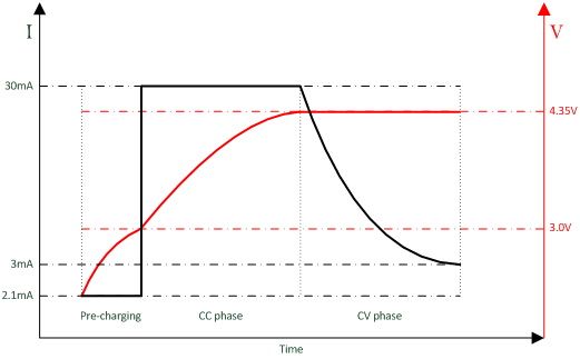
Figure 41 Battery charging profile
The configuration of the charger for this specific battery is listed in Table 36.
| Configuration settings | Values |
|---|---|
| dg_configBATTERY_TYPE |
(Since this Li-ion battery has a charging voltage level other than 4.2V, this is a custom battery.) |
| dg_configBATTERY_TYPE_CUSTOM_ADC_VOLTAGE | 3562 (4.35V) |
| dg_configBATTERY_CHARGE_VOLTAGE | 0xD (the hardware setting for 4.35V) |
| dg_configBATTERY_CHARGE_CURRENT | 2 (the hardware setting for 30mA) |
| dg_configBATTERY_PRECHARGE_CURRENT | 20 (the setting for 2.1mA) |
| dg_configBATTERY_LOW_LEVEL | 2496 (3.05V) |
13.5.5. Issues for non-rechargeable batteries
If the user uses a non-rechargeable battery, header files must be modified. In that case please contact Dialog Customer Support.
If the user uses a USB charger with an invalid battery type such as
BATTERY_TYPE_NO_RECHARGE or BATTERY_TYPE_NO_BATTERY the
compilation will be aborted with an error. When using a non-rechargeable
battery, the Hibernation option is disabled because of low voltage
detection.
13.6. Watchdog Service
13.6.1. Description
The system watchdog service (sys_watchdog) has been designed to monitor
system tasks and avoid system freezes. The interaction of this service
with other parts of the system is shown in Figure 42:
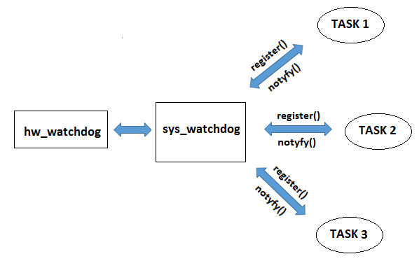
Figure 42 Watchdog overview
Effectively, sys_watchdog is a layer on top of the watchdog low-level driver that allows multiple tasks to share the underlying hardware watchdog timer. The watchdog service can be used to trigger a full system reset. This will allow system to recover from a catastrophic failure in one or more tasks.
13.6.2. Concept
A task that should be monitored has to first register itself with this
service to receive a unique handle (id). The task must then is
periodically notify sys_watchdog using this id, to signal that the task
working properly. In case of any error during registration, the invalid id
-1 is returned.
The hardware watchdog is essentially a countdown timer, which will
trigger a full system reset if it expires. To prevent this, the watchdog
timer must be reset to its starting value before it expires. This
starting value can be configured in the application custom configuration
files via the numerical macro dg_configWDOG_RESET_VALUE. Its default
value is the maximum 0xFF, which corresponds to approximately 2.6
seconds (the time unit is 10.24 msec). The maximum number of tasks that
can be monitored is defined by the configuration macro
dg_configWDOG_MAX_TASKS_CNT (the absolute maximum is 32).
If during one watchdog period all monitored tasks notify sys_watchdog,
the hardware watchdog will be updated via the
hw_watchdog_set_pos_val() LLD API function; in this case, no
platform reset will be triggered for this watchdog period. However, a
platform reset will be triggered if at least one task does not notify
sys_watchdog in time. There are two ways for a task to notify
sys_watchdog.
Each task is responsible for periodically notifying sys_watchdog that it is still running using sys_watchdog_notify(). This must be done before the watchdog timer expires. Occasionally a registered task may want to temporarily exclude itself from being monitored if it expects to be blocked for a long time waiting for an event. This is done using the sys_watchdog_suspend() API function. This function suspends monitoring of specific tasks in sys_watchdog, as there is no need to monitor a task that is blocked waiting for an event that might take too long to occur (i.e. it would lead to the task failing to notify the watchdog service, thus resulting in a system reset). When the task is unblocked, the sys_watchdog_resume() API function should be called to restore task monitoring by the watchdog service. From that moment on the task shall notify the watchdog service as usual.
Finally, the sys_watchdog_set_latency() API function is intended to be used in cases where a task would require a watchdog period greater than the configured watchdog timer reset value. Using this API allows a task to delay notification of sys_watchdog for a given number of watchdog periods, without triggering a system reset. The effect of calling the API function is one-off, thus it must be set every time increased latency is required.
Finally, the sys_watchdog_set_latency() API function is intended to
be used in cases where a task would require a watchdog period greater
than the configured watchdog timer reset value. Using this API allows a
task to delay notification of sys_watchdog for a given number of
watchdog periods, without triggering a system reset. The effect of
calling the API function is one-off, thus it must be set every time
increased latency is required.
13.6.3. Examples
To register the tasj with sys_watchdog use the following code snippet
/* register pxp task to be monitored by watchdog */
wdog_id = sys_watchdog_register(false);
To notify sys_watchdog use sys_watchdog_notify(). If the task is going to suspend for an event then temporarily exclude the current task from being monitored using sys_watchdog_suspend(). Once the task has received an event it can resume its watchdog operation with sys_watchdog_resume(). This flow is shown below :
/* notify watchdog on each loop since there's no other trigger for this - monitoring
* will be suspended while blocking on OS_TASK_NOTIFY_WAIT()
*/
sys_watchdog_notify(wdog_id);
/*
* Wait on any of the event group bits, then clear them all
*/
sys_watchdog_suspend(wdog_id);
ret = OS_TASK_NOTIFY_WAIT(0, OS_TASK_NOTIFY_ALL_BITS, ¬if, OS_TASK_NOTIFY_FOREVER);
/* Blocks forever waiting for the task notification.
Therefore, the return value must
* always be OS_OK
*/
OS_ASSERT(ret == OS_OK);
sys_watchdog_resume(wdog_id);
13.6.4. API
| Function | Description |
|---|---|
| void sys_watchdog_init(void) | Initialize This should be called before using the |
| int8_t sys_watchdog_register(bool notify_trigger) | Register current task with the sys_watchdog service. Returned identifier shall be used in all other sys_watchdog API calls from current task. Once registered, the task shall notify sys_watchdog periodically using sys_watchdog_notify() to prevent watchdog expiration. It is up to each task how this is done, but a task can request that it will be triggered periodically using the task notification capability, to notify sys_watchdog back as a response. |
| void sys_watchdog_unregister(int8_t id) | Unregister task from the sys_watchdog service. |
| void sys_watchdog_suspend(int8_t id) | Suspend task being monitoring by the A monitor-suspended task is not unregistered entirely, but it is ignored by the watchdog service until its monitoring is resumed. It is faster than unregistering and registering the task again. |
| void sys_watchdog_resume(int8_t id) | Resume monitoring of a task by the It should be called as soon as the reason that |
| void sys_watchdog_notify(int8_t id) | Notify sys_watchdog module about task. A registered task shall call this API function periodically to notify sys_watchdog that it is alive. This should be done frequently enough to fit into the watchdog timer interval set by dg_configWDOG_RESET_VALUE. |
| void sys_watchdog_set_latency(uint8_t id, uint8_t latency) | Set watchdog latency for a task. This allows a task to miss a given number of notification periods to |