15. Operation modes and startup procedure
The SmartSnippets™ DA1468x SDK supports two operational modes that correspond to the configurations described in 14.1.1.1 the SmartSnippets DA1468x SDK includes a number of operation modes that correspond to these configurations. They are:
The following operation modes are supported:
| Operation mode | Code location | Cache enabled | Description |
|---|---|---|---|
| RAM | RAM | No | Program is loaded directly to RAM. |
| Flash cached | Flash (quad SPI mode) | Yes | Program runs in-place from QSPI flash. The first 0x100 – flash image header size bytes are copied to RAM by the boot loader. |
15.1. Generated ELF file
After the project code is compiled, the linker generates an Extensible Linking Format (ELF) file based on the supplied linker scripts of each project (sections.ld and mem.ld). The following tables show the section structure (as obtained by the readelf utility with the -s option) for the three combinations of RAM mode with no Bluetooth low energy, flash cached mode with no Bluetooth low energy and flash cached mode with Bluetooth low energy.
The key difference with Bluetooth low energy support is the jump_table_mem_area section that holds pointers to callback functions used by the BLE ROM code.
.copy.table is used by the startup procedure in order to copy (load)
code and data sections onto RAM. The table contains one or more section
entries. The first 4 bytes in each entry are the section’s source
address, the next 4 bytes are the section’s destination address in RAM
and the last 4 bytes are the section’s size. Usually there are two
sections that are loaded onto RAM: the .data section and the
RETENTION_ROM0 section .zero.table works in a similar manner, but it
only writes zero’s to memory areas with zero-initialized data. Its
entries contain a destination address (4 bytes) and size (4 bytes). The sections that are initialized to zero are .bss and the zero-initialized part of RETENTION_RAM0.
| [Nr] | Name | Type | Addr | Off | Size | ES | Flg | Lk | Inf | Al |
|---|---|---|---|---|---|---|---|---|---|---|
| [0] | NULL | 00000000 | 000000 | 000000 | 00 | 0 | 0 | 0 | ||
| [1] | .text | PROGBITS | 07fc0000 | 008000 | 0055c4 | 00 | AX | 0 | 0 | 16 |
| [2] | .ARM.exidx | ARM_EXIDX | 07fc55c4 | 00d5c4 | 000008 | 00 | AL | 1 | 0 | 4 |
| [3] | .copy.table | PROGBITS | 07fc55cc | 00d5cc | 000018 | 00 | WA | 0 | 0 | 1 |
| [4] | .zero.table | PROGBITS | 07fc55e4 | 00d5e4 | 000018 | 00 | WA | 0 | 0 | 1 |
| [5] | .data | PROGBITS | 07fd8000 | 010000 | 000064 | 00 | WA | 0 | 0 | 4 |
| [6] | .bss | NOBITS | 07fd8064 | 018064 | 00020c | 00 | WA | 0 | 0 | 4 |
| [7] | .heap | PROGBITS | 07fd8270 | 018008 | 001c00 | 00 | 0 | 0 | 8 | |
| [8] | .stack_dummy | PROGBITS | 07fd8270 | 019c08 | 000200 | 00 | 0 | 0 | 8 | |
| [9] | RETENTION_ROM0 | PROGBITS | 07fd0000 | 018000 | 000008 | 00 | WA | 0 | 0 | 4 |
| [10] | RETENTION_RAM0 | NOBITS | 07fd0008 | 018008 | 001f58 | 00 | WA | 0 | 0 | 4 |
| [11] | RETENTION_RAM1 | PROGBITS | 00000000 | 019e08 | 000000 | 00 | W | 0 | 0 | 1 |
| [12] | .ARM.attributes | ARM_ATTRIBUTES | 00000000 | 019e08 | 000028 | 00 | 0 | 0 | 1 | |
| [13] | .comment | PROGBITS | 00000000 | 019e30 | 000070 | 01 | MS | 0 | 0 | 1 |
| [14] | .shstrtab | STRTAB | 00000000 | 019ea0 | 0000a8 | 00 | 0 | 0 | 1 | |
| [15] | symtab | SYMTAB | 00000000 | 01a1f0 | 003b40 | 10 | 16 | 642 | 4 | |
| [16] | strtab | STRTAB | 00000000 | 01dd30 | 001e73 | 00 | 0 | 0 | 1 |
Key to Flags:
W (write), A (alloc), X (execute), M (merge), S (strings)
I (info), L (link order), G (group), T (TLS), E (exclude), x (unknown)
O (extra OS processing required) o (OS specific), p (processor specific)
| [Nr] | Name | Type | Addr | Off | Size | ES | Flg | Lk | Inf | Al |
|---|---|---|---|---|---|---|---|---|---|---|
| [0] | NULL | 00000000 | 000000 | 000000 | 00 | 0 | 0 | 0 | ||
| [1] | .text | PROGBITS | 08000000 | 008000 | 004fb0 | 00 | AX | 0 | 0 | 16 |
| [2] | ARM.exidx | ARM_EXIDX | 08004fb0 | 00cfb0 | 000008 | 00 | AL | 1 | 0 | 4 |
| [3] | .copy.table | PROGBITS | 08004fb8 | 00cfb8 | 000018 | 00 | WA | 0 | 0 | 1 |
| [4] | .zero.table | PROGBITS | 08004fd0 | 00cfd0 | 000018 | 00 | WA | 0 | 0 | 1 |
| [5] | .data | PROGBITS | 07fc8000 | 010000 | 000064 | 00 | WA | 0 | 0 | 4 |
| [6] | .bss | NOBITS | 07fc8064 | 018064 | 000210 | 00 | WA | 0 | 0 | 4 |
| [7] | .heap | PROGBITS | 07fc8278 | 010e48 | 001c00 | 00 | 0 | 0 | 8 | |
| [8] | .stack_dummy | PROGBITS | 07fc8278 | 012a48 | 000200 | 00 | 0 | 0 | 8 | |
| [9] | RETENTION_ROM0 | PROGBITS | 07fc0100 | 010100 | 000d48 | 00 | WAX | 0 | 0 | 4 |
| [10] | RETENTION_RAM0 | NOBITS | 07fc0e48 | 010e48 | 001f54 | 00 | WA | 0 | 0 | 4 |
| [11] | RETENTION_RAM1 | PROGBITS | 00000000 | 012c48 | 000000 | 00 | W | 0 | 0 | 1 |
| [12] | .ARM.attributes | ARM_ATTRIBUTES | 00000000 | 012c48 | 000028 | 00 | 0 | 0 | 1 | |
| [13] | .comment | PROGBITS | 00000000 | 012c70 | 000070 | 01 | MS | 0 | 0 | 1 |
| [14] | .shstrtab | STRTAB | 00000000 | 012ce0 | 0000a8 | 00 | 0 | 0 | 1 | |
| [15] | .symtab | SYMTAB | 00000000 | 013030 | 004130 | 01 | 16 | 717 | 4 | |
| [16] | . strtab | STRTAB | 00000000 | 017160 | 002187 | 00 | 0 | 0 | 1 |
Key to Flags:
W (write), A (alloc), X (execute), M (merge), S (strings)
I (info), L (link order), G (group), T (TLS), E (exclude), x (unknown)
O (extra OS processing required) o (OS specific), p (processor specific)
| [Nr] | Name | Type | Addr | Off | Size | ES | Flg | Lk | Inf | Al |
|---|---|---|---|---|---|---|---|---|---|---|
| [0] | NULL | 00000000 | 000000 | 000000 | 00 | 0 | 0 | 0 | ||
| [1] | .text | PROGBITS | 08000000 | 008000 | 00c7f4 | 00 | AX | 0 | 0 | 16 |
| [2] | .ARM.exidx | ARM_EXIDX | 0800c7f4 | 0147f4 | 000008 | 00 | AL | 1 | 0 | 4 |
| [3] | jump_table_mem_ar | PROGBITS | 0800c7fc | 0147fc | 000240 | 00 | A | 0 | 0 | 4 |
| [4] | .copy.table | PROGBITS | 0800ca3c | 014a3c | 000018 | 00 | WA | 0 | 0 | 1 |
| [5] | .zero.table | PROGBITS | 0800ca54 | 014a54 | 000018 | 00 | WA | 0 | 0 | 1 |
| [6] | .data | PROGBITS | 07fc0100 | 018100 | 000074 | 00 | WA | 0 | 0 | 4 |
| [7] | .bss | NOBITS | 07fc0174 | 018174 | 001e28 | 00 | WA | 0 | 0 | 4 |
| [8] | .heap | PROGBITS | 07fc1fa0 | 01ffd0 | 000800 | 00 | 0 | 0 | 8 | |
| [9] | .stack_dummy | PROGBITS | 07fc1fa0 | 0207d0 | 000800 | 00 | 0 | 0 | 8 | |
| [10] | RETENTION_ROM0 | PROGBITS | 07fd6000 | 01e000 | 001fcc | 00 | WAX | 0 | 0 | 4 |
| [11] | RETENTION_RAM0 | NOBITS | 07fd7fcc | 01ffcc | 005df8 | 00 | WA | 0 | 0 | 4 |
| [12] | RETENTION_RAM1 | PROGBITS | 00000000 | 020fd0 | 000000 | 00 | W | 0 | 0 | 1 |
| [13] | RETENTION_BLE | NOBITS | 07fdec00 | 01ffcc | 001400 | 00 | WA | 0 | 0 | 1 |
| [14] | .ARM.attributes | ARM_ATTRIBUTES | 00000000 | 020fd0 | 000028 | 00 | 0 | 0 | 1 | |
| [15] | .comment | PROGBITS | 00000000 | 020ff8 | 000070 | 01 | MS | 0 | 0 | 1 |
| [16] | .shstrtab | STRTAB | 00000000 | 021068 | 0000ca | 00 | 0 | 0 | 1 | |
| [17] | .symtab | SYMTAB | 00000000 | 02142c | 00c510 | 10 | 18 | 2314 | 4 | |
| [18] | . strtab | STRTAB | 00000000 | 02d93c | 0086f5 | 00 | 0 | 0 | 1 |
Key to Flags:
W (write), A (alloc), X (execute), M (merge), S (strings)
I (info), L (link order), G (group), T (TLS), E (exclude), x (unknown)
O (extra OS processing required) o (OS specific), p (processor specific)
15.2. Program loading
15.2.1. RAM mode
A program built for RAM operation can be loaded to RAM either directly using the ELF file and J-Link debugger or be first converted to a raw binary and then written to RAM with the CLI programmer tool. RAM operation is used only for debugging purposes as it avoids the step of programming the QSPI flash. After loading the program, SYS_CTRL_REG must be configured so that RAM is mapped to address 0x00000000. After a soft reset is issued, the written program starts execution. RAM operation does not rely on the boot loader.
15.2.2. Flash cached mode
A program built for flash cached mode is written into QSPI flash memory with the CLI programmer tool. After a hard reset, the boot loader detects the valid program in QSPI flash and prepares to run it. When executing from flash, the first 0x100 virtual addresses are mapped to the beginning of RAM, i.e. memory area 0x00000000 – 0x000000ff is mapped to memory area 0x07fc0000 – 0x07fc00ff (SYS_CTRL_REG[REMAP_INTVECT] must always be set to 1). This ensures that ARM Interrupt Vector Table (IVT) is always in RAM memory for quick access.
The bootloader checks if the flash has a valid program by looking for the presence of a special header which is added to the image before the actual program. This header is added prior to writing the image into flash by the bin2image utility. The following tables describe the structure of the flash header.
| Address (byte) | Value | Description |
|---|---|---|
| 0:1 | ‘p’, ‘P’ or ‘q’, ‘Q’ | ASCII header to identify the functional mode of the device. “pP”: Mirrored mode (SPI) “qQ”: Cached mode (QSPI) |
| 2:3 | 0, 0 | Reserved |
| 4:7 | Any | Image length (big endian) |
Simply prepending the header to the binary image would shift the entire image in flash and corrupt the code as all the function addresses would be wrong. Instead, bin2image only modifies the first 0x100 bytes.
As shown in Figure 43, the reserved area that follows the IVT is reduced by the size of the flash header (H). This is harmless, since the contents of the reserved area are written after the program starts execution. After the boot loader detects the valid image in flash, it copies memory area [0x80000000 + H, – 0x800000ff] to RAM [0x07fc0000, 0x07fc00ff – H], thus skipping the header and placing the IVT in the beginning of RAM, restoring the reserved area to its original size.
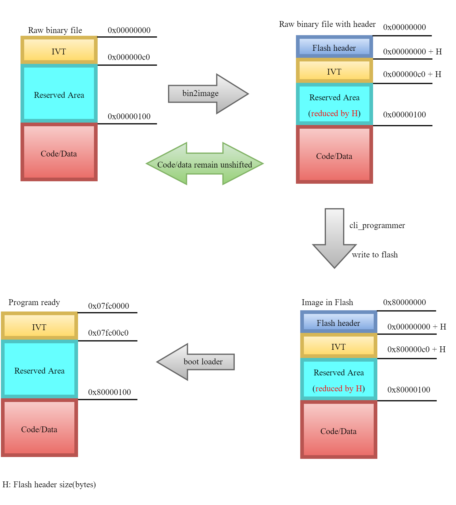
Figure 43 Flash cached pre-execution stages
15.3. BLE ROM patches
DA1468x employs special hardware to support BLE ROM patching. The patch controller is a memory address translator with 28 entries and it has additional registers for validating and invalidating entries. 20 of those entries are for patching BLE ROM functions, and the remaining 8 are for patching data. The patch controller intercepts memory read accesses from the processor. If the memory read address matches any of the addresses of the valid patch controller entries, a patch action is triggered.
For data patches, the patch controller simply redirects the read access to the address written in the entry’s data address register.
For function patches, the patch controller redirects execution to the corresponding function address at virtual memory location 0x000000C0 + N, where N (0 <= N < 20) is the index of the entry of the patch controller that has been triggered. This implies that virtual memory addresses 0x000000C0 to 0x0000010c must contain patch function addresses (4 byte aligned), if the corresponding entry of the patch controller is marked as valid. This is the reserved memory area described in the previous section after the IVT. The patch memory area includes 8 * 4 additional reserved bytes for a total size of 28 * 4 = 112 bytes. Its first 64 bytes reside in the Reserved Area in RAM as discussed previously in this document, and the remaining bytes are in flash memory (Bluetooth low energy applications do not support RAM operation mode), beginning at address 0x80000100.
15.4. Startup procedure
The startup procedure is the part of the program that runs after reset and before entering main(). It consists briefly of the following steps (please consult startup code within the SmartSnippets™ DA1468x SDK for details).
Reset_Handler in sdk\bsp\startup\startup_ARMCM0.S
- Deactivate cache and include it to available RAM (RAM operation only)
- Copy first
0x100 –Hbytes from Flash to RAM (Flash cached operation andflash offset = 0)
SystemInitPre() in sdk\bsp\startup\system_ARMCM0.c
- Enable debugger (if corresponding option is enabled)
- Enable Fast clocks
- Check alignment of copy and zero tables
SystemInit() in sdk\bsp\startup\system_ARMCM0.c
- Check IC version compatibility with SW
- Initialize TCS (see 25 for details on TCS contents)
- Activate BOD protection
- Configure interrupt priorities
- If executing from RAM ensure PMU is in a known good state
a.
- RC16 Clock setup
- Disable XTAL16M
- Set QSPI to highest speed
SystemInitPost() in sdk\bsp\startup\system_ARMCM0.c
- Start LDOs
- Set Radio voltage to 1.4V
- Initialize the QSPI flash (flash cached mode only)
- Read Trim values from OTP
- Apply Trim values from OTP
- Enable the QSPI Flash (flash cached mode only)
- Apply the System values from TCS
- Configure cache (flash cached mode only)
Reset_Handler in sdk\bsp\startup\startup_ARMCM0.S
Note
In RAM configuration these steps take place before SystemInitXXX() calls.
- Copy code and data to RAM according to
.copy.tablesection - Initialize certain memory areas to zero according to
.zero.tablesection
15.5. Secure Boot
Warning
Secure Boot support is available only for DA14683 devices – it is not supported for DA14681 devices.
Secure Boot is an alternative bootloader which could be used as a second stage bootloader during Software Update over the Air (SUOTA) procedure which supports:
- FW (firmware) Authentication: securely ensures validity and authenticity of entire Application firmware during booting.
- Rollback Prevention: prevents execution of out-of-date vulnerable code.
- Public Keys administration: Root keys being used for Integrity protection can be revoked.
Secure Boot depends on cryptographic Engines Low-level drivers only. Being the only thread running at boot time, it does not require thread-safe APIs from Security framework.
15.5.1. Features
Secure Boot Loader (SBL) is implemented in main_secure.c file located in: <sdk_root_directory>\sdk\bsp\system\loaders\ble_suota_loader. Figure 44 below presents Secure Boot’s main functionality.
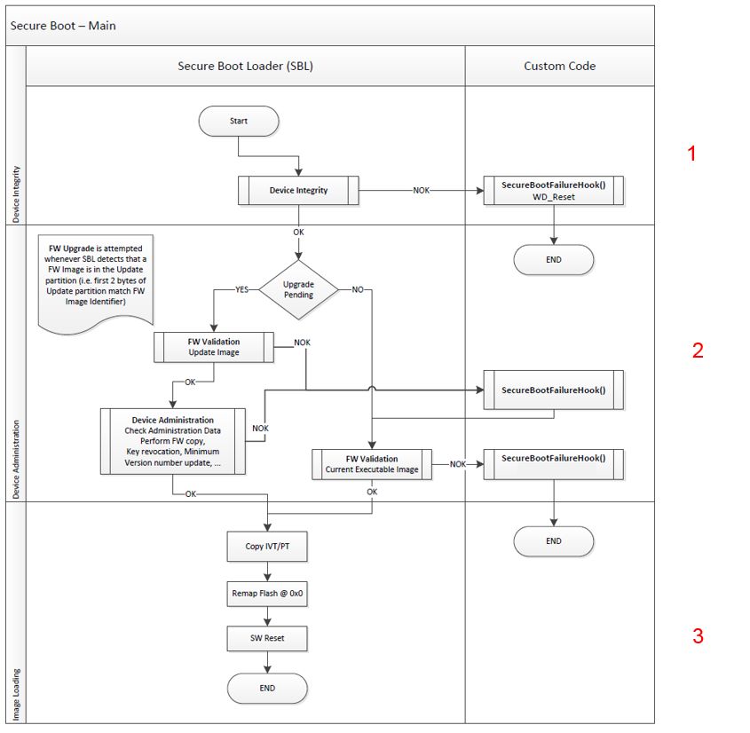
Figure 44 Secure Boot - Main
The Secure Boot Loader features:
Device Integrity, shown in Figure 45, is a feature of Secure Boot which:
- Compares bootloader’s CRC placed in OTP header with the calculated CRC
- Checks “Secure Device” field in OTP header (some functionalities of Secure Boot are available only for secured devices)
- Validates the symmetric keys stored in OTP and used in encryption/decryption
- Validates the root/public keys stored in OTP and used in image signature validation
- Checks minimum FW version image stored in the OTP
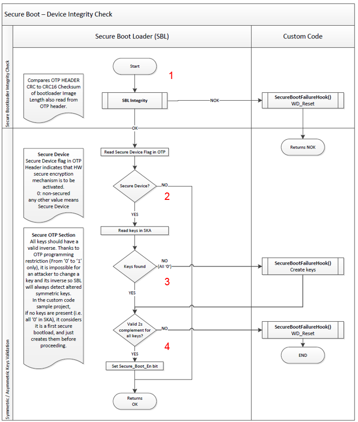
Figure 45 Secure Secure Boot – Device Integrity Check
Figure 46 shows the OTP layout:
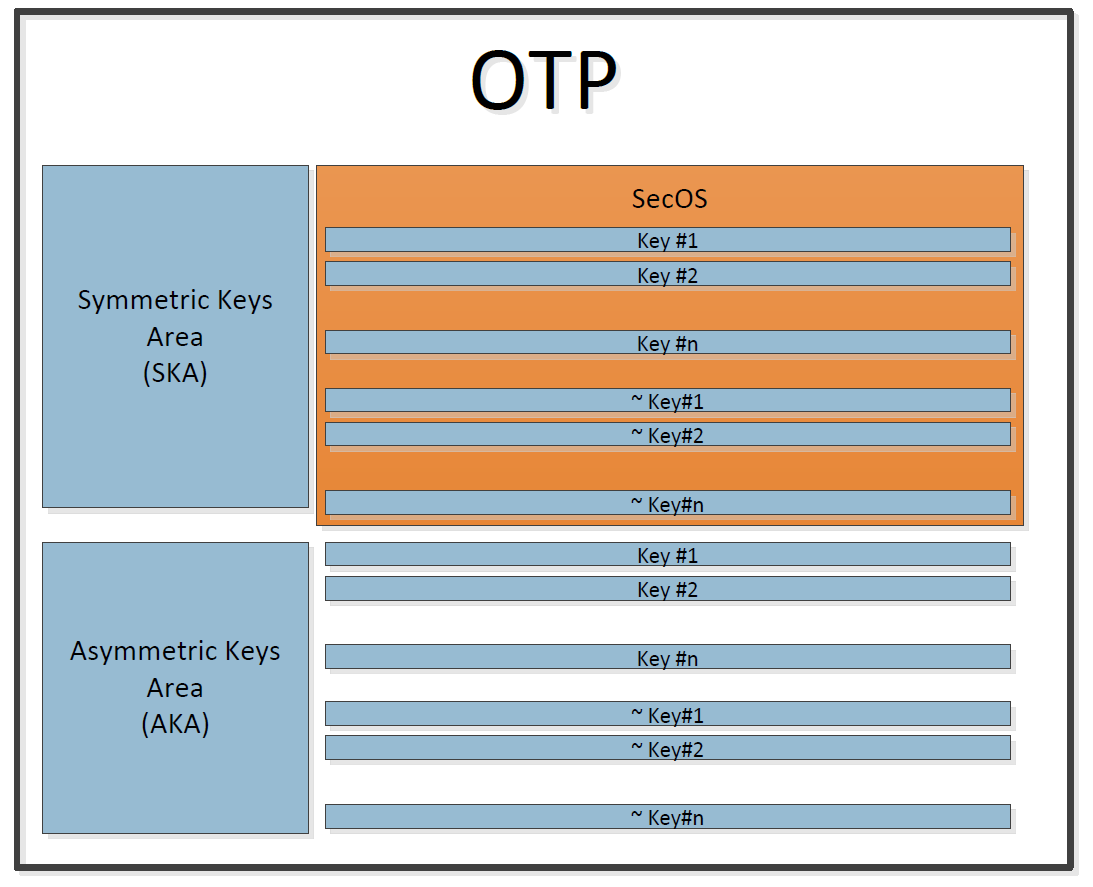
Figure 46 OTP layout
Firmware Validation , show in Figure 47, is a feature of Secure Boot which:
- Checks SUOTA 1.1 header
- Checks image’s CRC
- Validates the header of security extension content
- Checks FW version number with the current minimum FW version
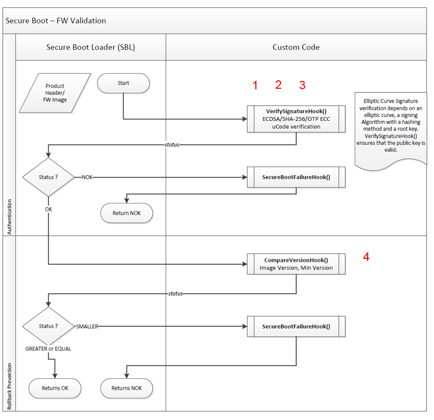
Figure 47 Secure Boot – FW validation
- Copying of the FW stored on the ‘update’ partition to the ‘executable’ partition (section 1, Figure 48)
- Upgrade of the minimum FW version array (section 2, Figure 48)
- Customizable code (hooks), (section 3, Figure 48 )
- Root/public keys revocation possibility (Figure 48)
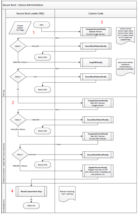
Figure 48 Secure Boot – Device Administration
Note
Secure Boot loader is stored in the OTP by default. Proper build configuration of the project must be used in order for the Secure Boot’s features to be available. Each configuration with _Secure suffix builds Secure Boot Loader as shown in Figure 49.
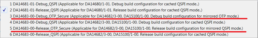
Figure 49 Secure Boot – Build Configurations
Secure Boot doesn’t use FreeRTOS and BLE. The SUOTA procedure must be handled by firmware - application image e.g. PXP Reporter. The installation and use of Secure Boot is described in the following section 15.5.2.
Note
For more info about SUOTA please refer to section 9 of [Ref_03]
15.5.2. Configuration
This section describes the installation and use of Secure Boot. At first user must import in the workspace of SmartSnippets™ Studio the following:
ble_suota_loaderproject. For more information about importingble_suota_loaderproject in SmartSnippets™ Studio please refer to [Ref_04].- Any application which supports SUOTA feature, e.g.
pxp_reporterdemo project with SUOTA support. For more information about importing and buildingpxp_reporterdemo application please refer to section 5 of [Ref_03]. - Python scripts. To import Python scripts into SmartSnippets™ Studio follow the same procedure as importing any other project in SmartSnippets™ Studio.
The list of the aforementioned projects, imported to SmartSnippets™ Studio is shown in Figure 50.
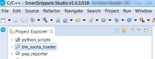
Figure 50 Secure Boot – IDE imported projects
User must follow next steps in order to install Secure Boot:
- Build firmware image of the imported application (e.g
pxp_reporter) using any mode (Release or Debug) with SUOTA support e.g.DA14683-00-Debug_QSPI_SUOTA. - Build
ble_suota_loaderproject usingDA14683-00-Release_OTP_Securebuild configuration (Figure 49). - Use
secure_image_config.pyPython script as show in Figure 51. Answering on few questions will be required during script execution as shown in next figures.
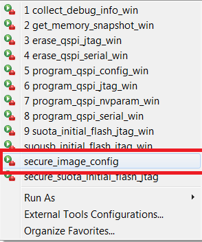
Figure 51 secure_image_config Python script
- First window after launching
secure_image_configscript is shown in Figure 52. By selecting “Yes” new product keys file is generated automatically.
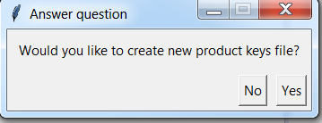
Figure 52 Question window to create new product keys file
- After selecting “Yes” in the previous dialog next window, Figure 53, pops out. User must decide, which type of elliptic curve would like to use for creating asymmetric keys. The curve will be used during an asymmetric key generation and image signature generation. After this procedure completes,
product_keys.xmlfile will be generated inpython_scriptsproject insecure_imagesubdirectory (Figure 54).
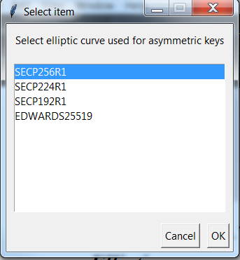
Figure 53 elliptic curves used for creating asymmetric keys
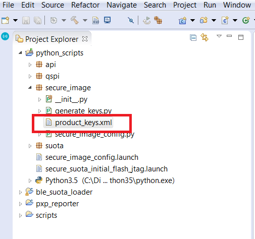
Figure 54 generated product_keys.xml file
Note
User may need to refresh workspace (or hit F5) in order to make product_keys.xml file visible
Note
By selecting “No” in Figure 53 the user must provide the private key manually by inserting a private key index and its value as shown in Figure 55 and Figure 56.
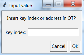
Figure 55 inserting private key index or address
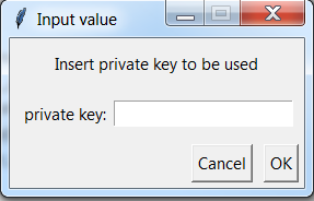
Figure 56 inserting private key value
- In this step the user decides to create private key manually (by answering “NO”) or automatically (by answering “YES”) by choosing it from existed
product_keys.xmlfile (Figure 57).
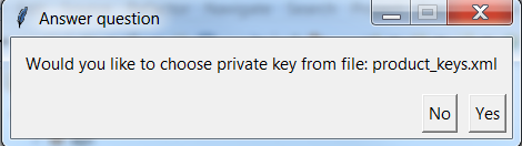
Figure 57 window to select the use of private key
- User must select one public key index as shown in Figure 58 which will be used during image signature validation (on the platform). Public keys should be stored in a proper order in the OTP memory.
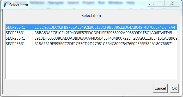
Figure 58 selecting private key from product_keys.xml files
- To each public key index a private key is assigned. This private key is then used during image signature generation. If
product_keys.xmlfile already exists then the user is prompted to create a newproduct_keys.xmlfile with new keys and save old keys inproduct_keys.xml.oldfile (Figure 59).
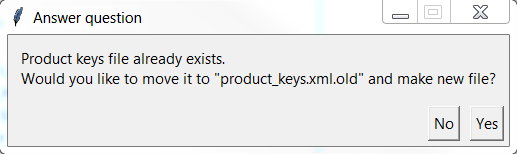
Figure 59 move existing configuration to product_keys.xml.old file
- For
SECP256R1,SECP224R1orSECP192R1types of curves hash method must be selected (Figure 60). In case ofEDWARDS25519it is not needed because by default this curve usesSHA-512. It will be used during image signature generation.
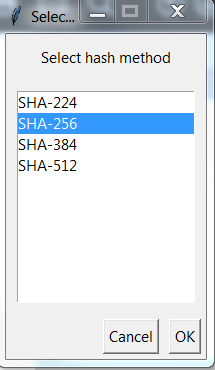
Figure 60 selecting hash method for SECP256R1, SECP224R1 or SECP192R1
- In this optional step, shown in Figure 61, the user can enter public key index/indexes or address/addresses (Figure 62) which will be revoked after image validation on the platform. Allowed values are number of indexes of asymmetric keys (0 – 3 for DA1468x Platform) or addresses of symmetric keys (s0 – s7 for DA1468x Platform).
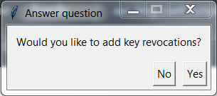
Figure 61 add key revocations selection
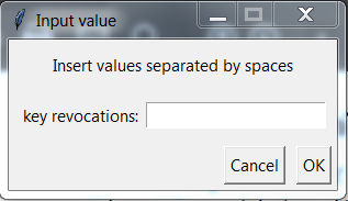
Figure 62 key revocations values window
- In this step the user can add minimal SW version on the platform (this is optional) as shown in Figure 63. This will be done after image validation on the platform. If the user doesn’t write any version in the window show in Figure 64, then SW version of the used image will be used as new minimal SW version.
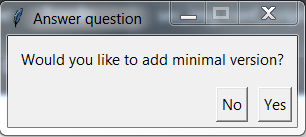
Figure 63 adding minimal version of software version
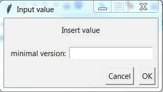
Figure 64 inserting minimal value of software
- Use
secure_suota_initial_flash_jtagpython script as shown in Figure 65. This script is used to save all generated keys and the secure bootloader in OTP memory and then flash the selected application in secure mode into DA1468x board.
Note
Before launching the secure application (e.g. pxp_reporter) ble_suota_loader must be first built with the following modes:
ble_suota_loaderin Release mode –DA14683-00-Release_OTP_Secure.pxp_reporterin any kind of mode with SUOTA support e.g. –DA14683-00-Debug_QSPI_SUOTA.
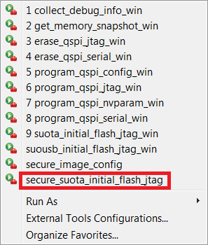
Figure 65 secure_suota_initial_flash_jtag script
15.5.3. Files
When the configuration procedure (described in 15.5.2) of Secure Boot ends two xml files are created: product_keys.xml (Figure 67) file and secure_img_cfg.xml (Figure 68) as shown in Figure 66.
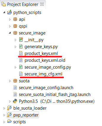
Figure 66 Secure Boot - generated files
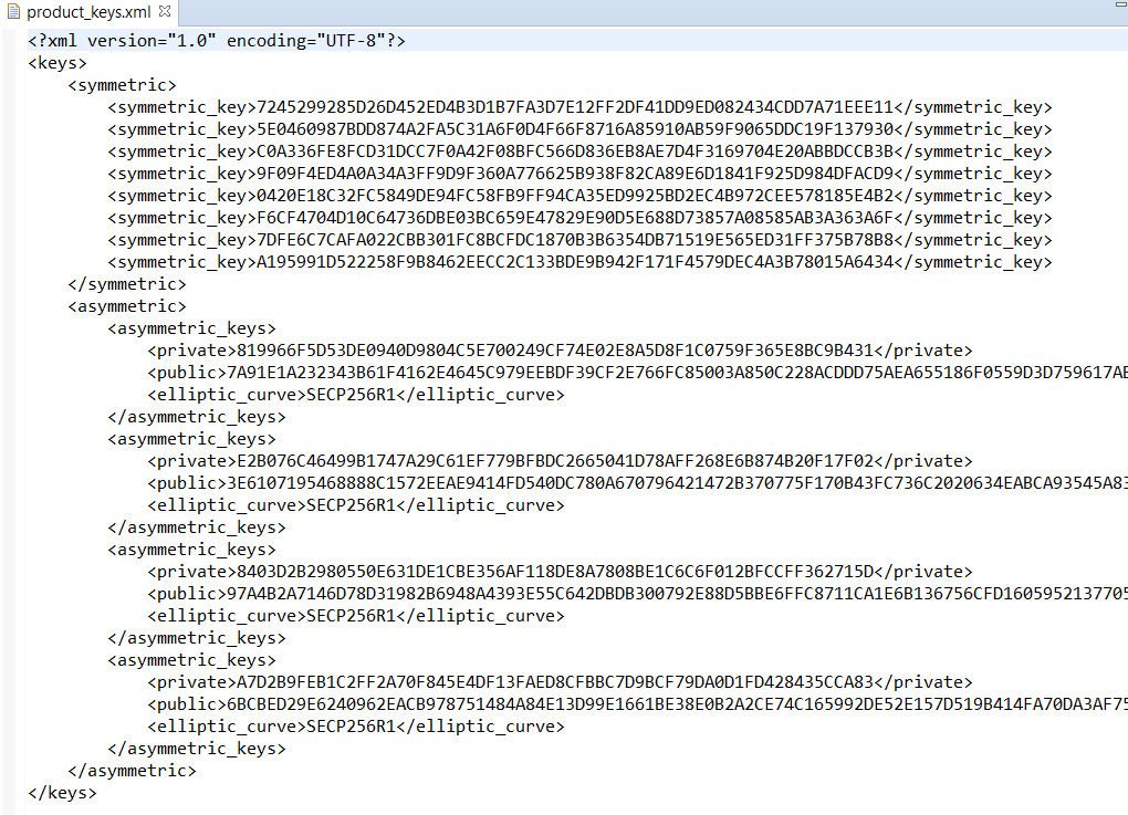
Figure 67 product_keys.xml file
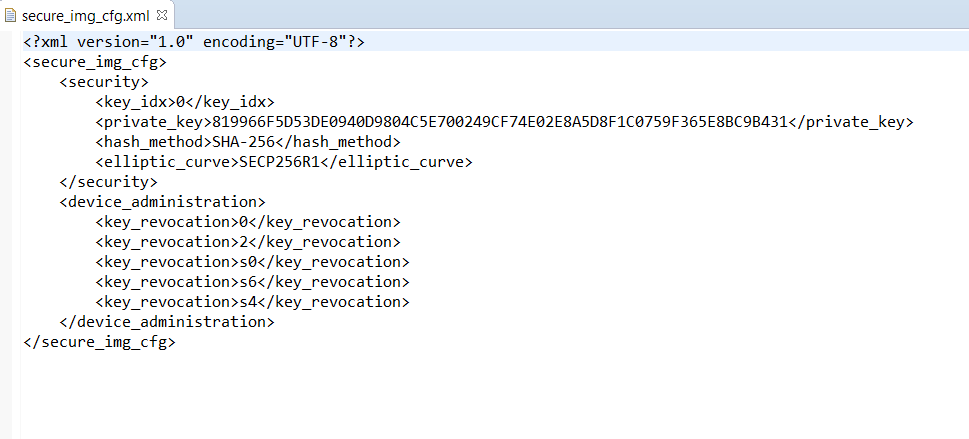
Figure 68 secure_img_cfg.xml file
These files are used by other scripts (e.g. secure_suota_initial_flash_jtag and mkimage) as input files.
Warning
initial_flash.py script performs writing to the One Time Programmable (OTP) memory. When this procedure is called with invalid configuration/firmware/bootloader files then the device may become unusable!
See also
For more info about SUOTA please refer to section 9 of [Ref_03].
Note
Scripts are using Python 3.