12. Your First DA1468x Application – Blinky
12.1. Introduction
The following sections explain how the user can build, program and run a simple software application called Blinky on the ProDK development board using the SmartSnippets™ DA1468x SDK.
This application is based on a pre-defined project template called
freertos_retarget_template which is located at
<sdk_root_directory>\projects\dk_apps\templates. After modification the
application will toggle an on-board LED with a pre-defined frequency.
The application is first described, then step by step instructions are given to build and run it.
12.2. Software Architecture
TThe freertos_retarget_template project is set to run in release mode
from DA1468x internal RAM by default. This is the easiest setup and does
not need any flash programming prior to executing the binary.
When the application starts running the first thing that is executed is
the Reset_Handler, which is located in startup > startup_ARMCM0.s. This
is followed by setting IRQ priorities and initializing variables.
Next, code execution continues with the main subroutine in file main.c. Here, trim values are applied to the DA1468x device. When the clock has been set up properly, the main routine creates task SysInit and starts the RTOS scheduler. Now the RTOS scheduler is running it will start its first task which is SysInit.
In the SysInit task the power and clock management module is started.
Next, the hardware peripherals which are used by this particular project
are initialized. This includes setting up the correct GPIOs, enabling
clocks and setting initial values to the hardware peripherals in use.
Last thing done before SysInit task exits is to create another task
which is the main application task running until the program gets
stopped. The function code implementing the main task is as follows:
static void prvTemplateTask( void *pvParameters )
{
OS_TICK_TIME xNextWakeTime;
static uint32_t test_counter=0;
        /* Initialise xNextWakeTime - this only needs to be done once. */
        xNextWakeTime = OS_GET_TICK_COUNT();

        for( ;; )
        {
         /* Place this task in the blocked state until it is time to run again.
         The block time is specified in ticks, the constant used converts ticks
         to ms.  While in the Blocked state this task will not consume any CPU
         time. */
         vTaskDelayUntil( &xNextWakeTime, mainCOUNTER_FREQUENCY_MS );
         test_counter++;

 if (test_counter % (1000 / OS_TICKS_2_MS(mainCOUNTER_FREQUENCY_MS)) == 0) {
                printf("#");
               fflush(stdout);
         }
        }
}
The software as provided in the SmartSnippets™ DA1468x SDK – once up and running - interacts with a host PC and sends the character ‘#’ via the serial UART interface every 1sec. This can be verified by setting up a terminal application (see 10.3.3 for the procedure, with the only difference that now the baud rate must be set to 115200).
The software shall be modified to toggle LED D2 every 200ms (Figure 4),
connected to pin P1_5.

Figure 33 LED D2 on ProDK
The software first needs to reserve and initialize the selected GPIO.
This typically takes place inside the periph_init() routine which is
located inside the main.c file. This is done by adding the following
code to the end of this function:
hw_gpio_set_pin_function(HW_GPIO_PORT_1,HW_GPIO_PIN_5, HW_GPIO_MODE_OUTPUT, HW_GPIO_FUNC_GPIO);
This call makes sure pin 5 of port 1 is set as GPIO output. To toggle
the GPIO every 200ms the main routine inside the prvTemplateTask()
routine needs to be modified as follows:
for( ;; )
             {
/* Place this task in the blocked state until it is time to run again. The block time is
   specified in ticks, the constant used convertsticks to ms. While in the Blocked
       state this task will not consume any CPU time. */
                        vTaskDelayUntil( &xNextWakeTime, mainCOUNTER_FREQUENCY_MS );
                        test_counter++;

                        /* make sure P1_5 is set and reset alternatively */
                        if(test_counter % 2)
                                hw_gpio_set_active(HW_GPIO_PORT_1, HW_GPIO_PIN_5 );
                        else
                                hw_gpio_set_inactive(HW_GPIO_PORT_1, HW_GPIO_PIN_5 );
                }
In Code 3 the if statement has been modified. The routines
(hw_gpio_set_active() and hw_gpio_set_inactive()) are an example of how
to use low level drivers (LLD). These APIs are defined in hw_gpio.h
(located in <sdk_root_directory>/peripherals/include).
12.3. Software Build
As already described in the previous section the SmartSnippets™ DA1468x SDK contains a template project featuring the FreeRTOS OS which will be used as a starting point to develop a customized SW project for the DA1468x family of devices. This section describes all the steps required to import, build and run this first project.
- In the SmartSnippets™ Studio welcome page click on the IDE icon from the Tools tab as shown in Figure 34.
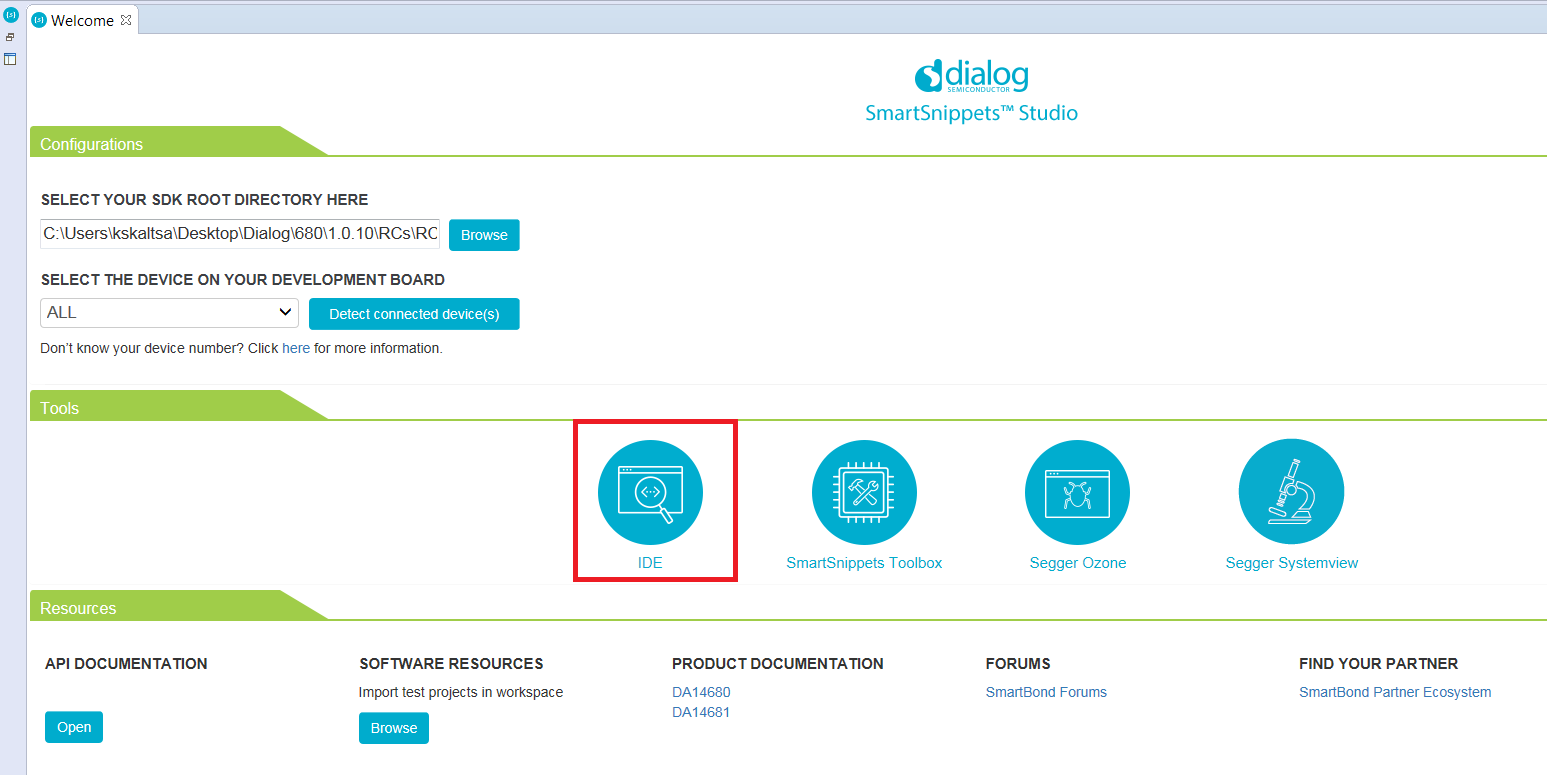
Figure 34 SmartSnippets™ Studio welcome page
- Import the template project template_freertos_retarget from:
<sdk_root_directory>\projects\dk_apps\templates\freertos_retargetinto the selected workspace. Press the browse button highlighted in the Resources tab (reference 1) and navigate to the folder which contains the specific project as shown in Figure 35.
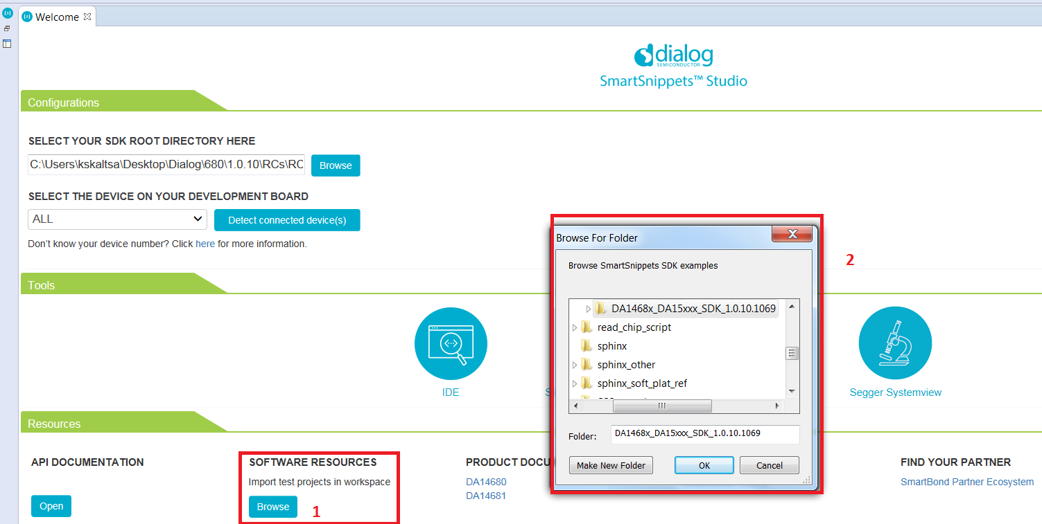
Figure 35 Project import
In the same way import the scripts project from:
<sdk_root_directory>\utilities\scriptsModify the file
main.cusing the text editor inside Eclipse and save the changes. Replace the Code 1 inprvTemplateTask()function with Code 3 as described in detail in 12.2.Extend
periph_init()function insidemain.cto set the function for the pin driving the external GPIO by adding Code 2 as described in detail in 12.2.
12.3.1. Build the project to run from RAM
The first build to try is a RAM build. This is the simplest one as there is no need to write the code to external QSPI flash, the debugger will load it directly into RAM from where it can be run. This is not the normal method of development.
Build the project with the Build button (reference 1 in Figure 36) with the Release RAM
configuration DA14681-01-Release-RAM as shown in Figure 36.
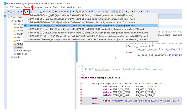
Figure 36 Build Blinky in Release RAM configuratione
Once the Release RAM binary is built, the next step is to start the Debugger using Run > Debug Configurations > SmartBond “SmartSnippets DA1468x SDK via J-Link GDB Server > RAM as shown in Figure 37. As this is a RAM build the debugger will download the binary file via J-Link debugger into the system RAM. To enable this the system RAM is mapped to address 0 by the debugger.
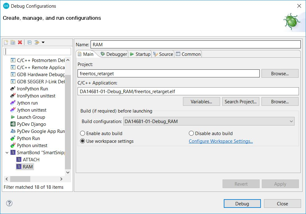
Figure 37 Start Debug in RAM mode
12.3.2. Build the project to run from QSPI Flash
- This will be the normal development flow which has three steps: build the code, write it to QSPI flash and then run it in the debugger.
- Build the project using the build icon (reference 1 in Figure 38) and select a QSPI configuration as shown in Figure 38.
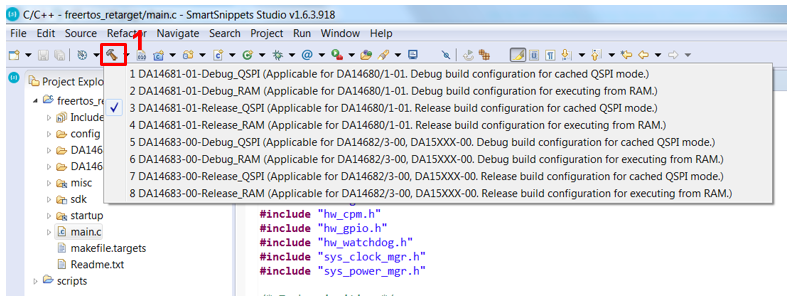
Figure 38 Build Blinky in Release QSPI configuration
The next step is to write the binary file to QSPI Flash. This is done
using a script selected using the External Tool Configurations button.
In Figure 39 the script program_qspi_jtag_win is used to program the
QSPI Flash memory. Alternatively, use Run > External Tools >
program_qspi_jtag_win.
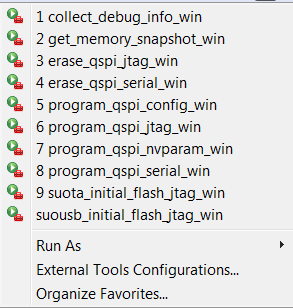
Figure 39 Write Blinky to QSPI Flash
On a Linux machine the equivalent options are suffixed with _linux
rather than _win. So, use program_qspi_jtag_linux instead.
Finally start the debugger using Run >Debug configurations > Smartbond “SmartSnippets DA1468x SDK” > QSPI and click ‘Debug’ as shown in Figure 40. This will start the debug perspective in Eclipse and load the symbols for the current project into the debugger.
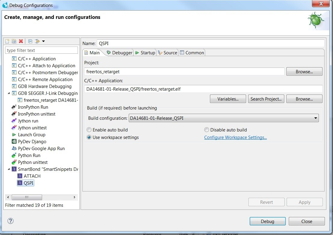
Figure 40 Start Debug in QSPI mode
12.4. Running the project in the Debugger
- Now that the binary has been loaded to memory (either RAM by debugger or QSPI by script) and the debugger has the symbols for the project loaded it is possible to run project in the debugger.
- Start execution of the
Blinkyproject by selecting Resume inside the Eclipse Run menu or by hitting the play icon as indicated in Figure 41.
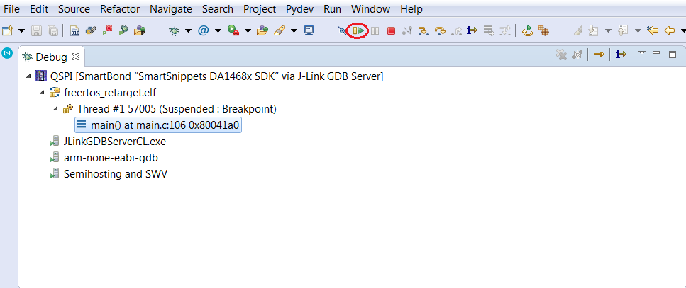
Figure 41 Executing the Blinky project in Eclipse
- Correct functionality of the built and downloaded Blinky project can be checked by watching the Orange LED D2 on the ProDK board (Figure 42). It should now blink with a frequency of around 2Hz.
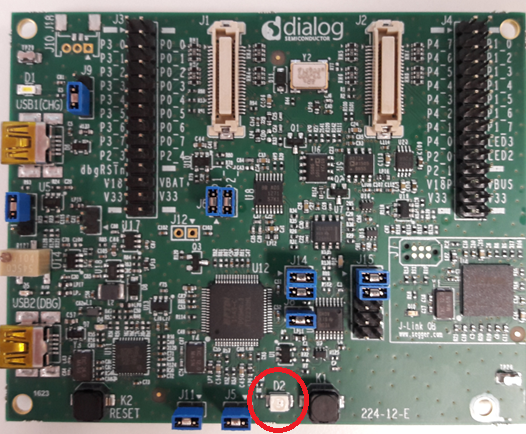
Figure 42 LED D2 - Pro DK
12.5. Troubleshooting
| Issue | Note |
|---|---|
Software execution stopped at
ASSERT_WARNING(is_compatible_chip
_version()); |
Project has not been compiled
using the correct silicon
version. Make sure the following
parameters have been properly
configured. (By default silicon
version is taken care by the
corresponding build
configuration). Make sure
parameter
dg_configBLACK_ORCA_IC_STEP and
dg_configBLACK_ORCA_IC_REV are
set to the correct chip revision
and the ProDK version during
built. (Located in
<sdk_root_directory>/bsp/config/b
sp_definitions.h) |
| LED does not blink | The GPIO which was used to drive
the external LED was P1_5 for
this sample code. This might have
to be adopted in case a different
revision of the ProDK board is in
use. To find the correct pin for
your version of the ProDK board
please check the [Ref_05] for details.
Make also sure that
dg_configBLACK_ORCA_MB_REV is set
to the correct chip revision and
the ProDK version during built.
.(Located in
<sdk_root_directory>/bsp/config/b
sp_definitions.h
) |