10. DA1468x – Software Installation
10.1. Introduction
This Section describes the installation procedure for the drivers, the configuration of the serial port, and all necessary steps to verify the connection with the PC as well as solutions to any problems that may occur.
10.2. Requirements of the Development PC
For proper evaluation and application development using the DA1468x SoC and the ProDK an external host is required. This external host must have an operating system already installed (Windows or Linux) and USB ports as described in 7.
Internet connectivity is also highly recommended for proper driver and software installation.
10.3. Driver installation
10.3.1. Microsoft Windows
On the first connection to a host PC which is running Microsoft Windows and has Internet connectivity, the system will detect several devices and will automatically install all necessary drivers. If the system is configured to use Windows Update, this process may need several minutes to be finished.
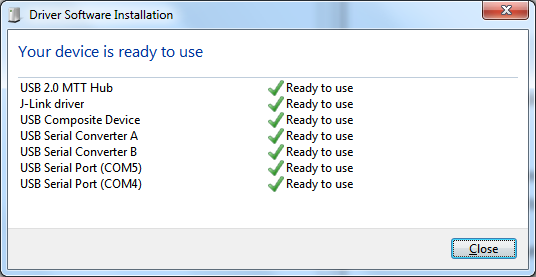
Figure 4 Windows driver installation
After driver installation is successfully completed, the system will pop-up a window similar to the one presented in Figure 4.
Note
The COM port number assigned to the newly attached ProDK mainboard might be different than the one shown in Figure 4 where the assigned COM port numbers are COM4 and COM5.
The COM port number can be found in Device Manager (Control Panel > Device Manager > Ports (COM & LPT)) as shown in Figure 5.
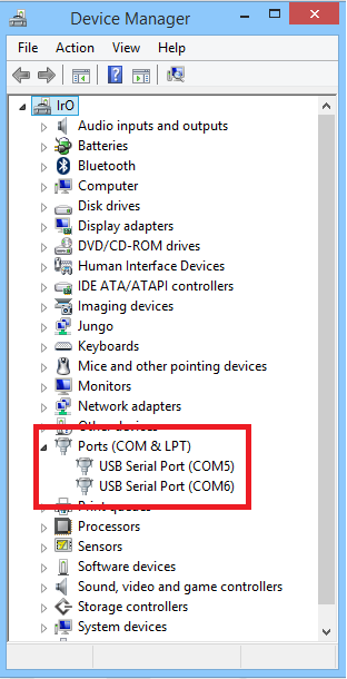
Figure 5 Device Manager Ports
10.3.2. Linux
When ProDK is connected to a host PC running a Linux distribution (such as Ubuntu or CentOS) and has Internet connectivity, the system will detect several devices and all necessary drivers will be silently installed. Provided that the process has properly finished, two additional devices will appear in the /dev directory under the names ttyUSB0 and ttyUSB1, as shown in Figure 6. These names might be different in case other serial converters are connected to the system beforehand. If no other serial port converters are connected, the device that should be used with the terminal or programmer utility will be called /dev/ttyUSB0. If there are more devices with the name ttyUSBx, note which ones showed up when the ProDK was connected and use the lower number of the two devices.
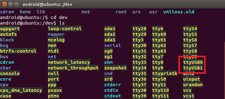
Figure 6 Ports assigned to ProDK
10.3.3. COM port usage
There are two virtual COM ports created by the driver with either
Windows or Linux. The first (lower number) is used to export a UART from
the DA1468x device. In the previous sections this was either COM4 or
/dev/ttyUSB0. The second (higher number) is used to export measurement
data from the current sense circuitry on the ProDK [Ref_05] to the Power
Profiler tool [Ref_06].
10.4. Configuring the serial port for UART1
Several development tools require UART1 to be routed to the FTDI serial port. Please refer to [Ref_05] for details on how to properly configure the specific port. ProDK board connection verification can be made using the pre-existing Terminal application.
10.4.1. Windows Host
On a Windows Host the utility RealTerm can be used to fully validate the connection to the ProDK
To make sure that the communication between the ProDK board and the development host is properly established, it is necessary to verify the UART connection between the two nodes. To do so, execute the following steps:
- Connect the ProDK board to the PC board via USB cable to USB2(DBG) as described in Paragraph 9.3 above.
- Verify that the host discovered two serial ports – the first of which connected to UART1 (see section 10.3.3).
- Start a terminal software with HEX display capabilities ( Figure 8, Reference points 2 and 3) (i.e. RealTerm)
- Open the serial port (Figure 8, Reference points 4 and 5) which
corresponds to ProDK UART1 (i.e. COM4 for Windows or
/usb/ttyUSB0for Linux), using the parameters shown in Table 1:
| Settings | Values |
|---|---|
| Baud rate | 57600 |
| Data bits | 8 |
| Parity | None |
| Stop bits | 1 |
| Handshaking | None |
- Click K2 RESET button on the ProDK board as depicted in Figure 7. If terminal shows bytes (non-printable characters) similar to those presented in Reference point 1 in Figure 8 on every reset button push, the connection has been correctly setup and the programmer can be used (sometimes other characters bytes can be sent). The sequence shown in Figure 8 is a confirmation sequence corresponding to a correct setup confirmation. The sequence is generated by the Bootloader [Ref_07] and corresponds to an ASCII string with the chip version.
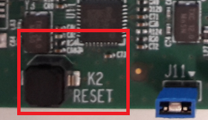
Figure 7 K2 RESET button in ProDK
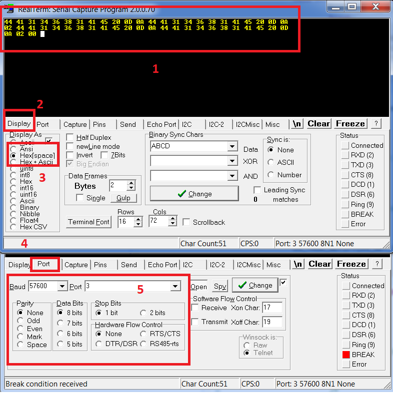
Figure 8 Setting port and testing connectivity via RealTerm
Note
to verify the chip version user can select ASCII display option. After clicking the K2 reset button the chip version is printed four times, as shown in Figure 9.
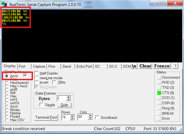
Figure 9 Chip version in RealTerm in Windows
10.4.2. Linux Host
Under Linux there is a simpler approach to validate the connection using
a basic terminal such as putty. Connect putty to /dev/ttyUSB0 at 57600
baud and press K2 Reset. There should be an output as shown in Figure 10
which contains ASCII characters with the device name as well as
non-ASCII characters. This is enough to validate the connection to
UART1.
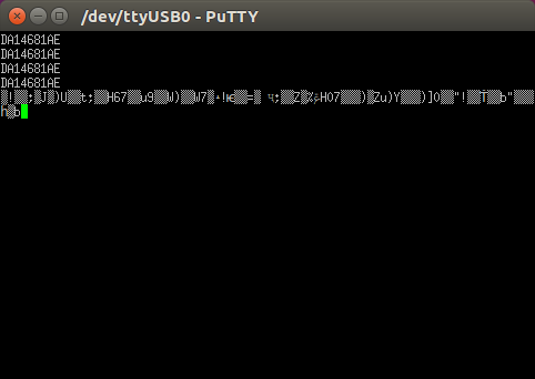
Figure 10 Chip version in PuTTY in Linux
10.5. Troubleshooting
If there any problems with the ProDK connection to PC some possible solutions might be:
- Make sure that the Host PC is connected to Internet
- Make sure that no old FTDI drivers are installed
- Check for possible cabling issue by using a different USB cable
- Connect the two elements using a different USB port on the host PC
Note
If none of these actions resolved the issue, please contact Dialog Software Forum.