6. Hardware Description
This section gives an overview of the design architecture of the IoT MSK. For further reading more details are provided in UM-B-095.
6.1. PCB and Board Layout:
The top view layout of the IoT MSK is shown in Figure 3. The IoT MSK Enclosure Bottom/Top view is given in Appendix B.
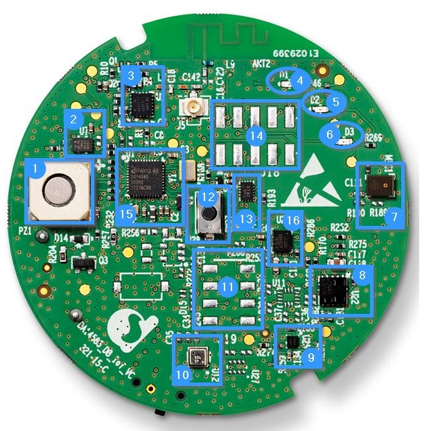
Figure 3 PCBA of a DA14585 IoT MSK: Top View
| Reference | Device Name | Description |
|---|---|---|
| 1 | CSS-I4B20-SMT | Magnetic buzzer transducer from CUI INC. |
| 2 | U7: MX25R2035FZUIL0 | Serial NOR Flash memory |
| 3 | U2: SKY66111-11 | Power Amplifier from Skyworks |
| 4 | D1: Yellow LED | LED |
| 5 | D2: Red LED | LED |
| 6 | D3: Green Led | LED |
| 7 | SPK0838HT4H-B | Digital microphone with a single-bit PDM output from Knowles |
| 8 | U22: VCNL4010 | Ambient light and IR proximity sensor from Vishay |
| 9 | U25: AK09915C | Magnetic sensor from Asahi Kasei |
| 10 | U12: BME680 | Environmental and Gas Sensor from Bosch |
| 11 | J19: 8 Expansion slot | Connection slots to connect additional peripheral and sensors modules |
| 12 | User Push Button | General purpose push button |
| 13 | U21: FXL6408UMX | I2C-controlled GPO expander from Fairchild |
| 14 | J18: 10 Expansion slot | Connection slots to connect additional peripheral and sensors modules |
| 15 | U1: DA14585 | Bluetooth Smart SOC |
| 16 | U24: ICM42605 | Accelerometer/Gyroscope Sensor from TDK Invensense |
The bottom view of the PCBA of DA14585 IoT MSK is shown in Figure 4.
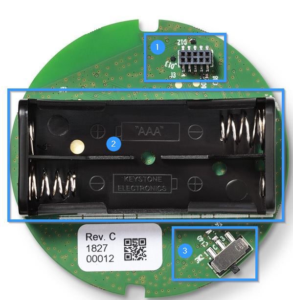
Figure 4 PCBA of DA14585 IoT MSK: Bottom View
| Reference | Device Name | Description |
|---|---|---|
| 1 | Port | Debugging Connector |
| 2 | Battery | 2x AAA Battery Holder |
| 3 | Switch | Power ON/OFF switch |
6.2. Sensors Overview
The IoT MSK includes an accelerometer/gyro sensor, digital microphone, Gas (CO2) sensor, and an infrared proximity combined with an ambient
light sensor in a single package. These sensors which can be accessed from the IoT MSK over the I2C, SPI, and PDM (Audio) interfaces.
For further reading The schematic of these sensors is available in this Document.
6.2.1. Environmental Sensor
The DA14585 IoT MSK employs the BME680 from Bosch Sensortec to detect environmental changes such as temperature, humidity, atmospheric pressure, and b-VOC. This highly compacted sensor is suitable for monitoring indoor air quality and can detect air contamination from paint, furniture, garbage, and others, using volatile oxide compound (VOC) levels. From the VOC readings, two air quality parameters can be displayed using smart algorithms: the indoor air quality index (AQI) and the breath b-VOC. This sensor is connected to DA14585 via an I2C interface.
6.2.2. Motion Sensor: Accelerometer/Gyroscope
The DA14585 IoT MSK employs the ICM42605 motion sensor from TDK Invensense that combines a 3-axis gyroscope and a 3-axis accelerometer with the following features:
- user-programmable interrupts
- wake-on-motion interrupt for low power operation of applications processor
The ICM42605 module is connected to DA14585 via an SPI interface which supports speeds up to 24 MHz.
Note
In full operation mode with the accelerometer and gyroscope enabled, the current consumption is typically 0.72 mA. This drops to 11 μA in sleep mode.
Note
For additional flexibility, the DA14585 IoT MSK is equipped with an additional PCB footprint of an alternative accelerometer/gyroscope sensor: BMI160. The ICM42605 should be unsoldered before using BMI160.
6.2.3. Audio Sensor: Microphone
The SPK0838HT4H-B from Knowles is a miniature, high-performance, low-power, and top-port silicon digital microphone with a single-bit PDM output. Due to its high power consumption in sleep mode, it is supplied via a dedicated GPO from the GPIO expander.
Warning
The microphone is not supported by the software reference applications provided with the DA14585 IoT MSK.
6.2.4. Electronic Compass (Magnetometer)
The DA14585 IoT MSK employs an electronic compass (magnetometer) sensor from Asahi Kasei, the AK09915C. It incorporates:
- a magnetic sensor for detecting terrestrial magnetism in the X-axis, Y-axis, and Z-axis
- a sensor driving circuit
- a signal amplifier chain
- an arithmetic circuit for processing signals from each sensor off-loading the main processing unit
- self-test function
The magnetic sensor is connected to the DA14585 via an SPI interface.
6.2.5. Barometric Pressure Sensor
The DA14585 IoT MSK employs a high-accuracy, low-power, and waterproof barometric pressure sensor from TDK InvenSense, ICP10100, for atmospheric pressure detection. This barometric pressure sensor is connected to DA14585 via an I2C interface.
Warning
This sensor is not mounted on this reference design and is not supported by the software reference applications provided with the DA14585 IoT MSK. Users wanting to use this sensor need to do the soldering themselves.
6.2.6. Optical Sensor: Ambient Light and IR Proximity
The DA14585 IoT MSK has an on-board ambient light and IR proximity sensor from Vishay, VCNL4010. This sensor is fully integrated as the IR LED emitter is included in the package. It is connected to DA14585 via the I2C interface.
Potential applications include:
- display contrast/brightness control
- proximity switch for consumer electronics, display, and devices
- dimming control
6.3. Buttons and LEDs
The IoT MSK is equipped with a general purpose user push button and three LED indicators. Table 3 shows the GPIO (DA14585 GPIO and the I2C GPIO expander) pin assignment.
| GPIO | Function |
|---|---|
| GPIO Expander GPO 0 | Yellow LED |
| GPIO Expander GPO 2 | Red LED |
| GPIO Expander GPO 4 | Green LED |
| P1_3 | Push button |
Note
When the kit is powered, the Yellow LED will blink for 60 seconds. During this time, the device will advertise. After 60 seconds, the device enters sleep mode and will only start advertising again when movement is detected.
Note
The user push button is active-low and is de-bounced by an RC filter with a time constant of about 2 ms.
6.4. NOR Flash Memory
The DA14585 IoT MSK uses an external Serial NOR Flash memory to mirror its contents to RAM and execute the content. The Flash memory type is MX25R2035FZUIL0.
- 2-Mbit QSPI Flash memory, operated in single I/O mode.
- Operating voltage: 1.65 V to 3.6 V for read, erase, and program operations.
- 8USON package.
| GPIO | Function |
|---|---|
| P0_0 (SPI_CLK) | SPI clock |
| P0_3 (SPI_CS) | SPI chip select |
| P0_6 (SPI_MOSI) | SPI_MOSI |
| P0_5 (SPI_MISO) | SPI_MISO |
Note
A pull-up resistor has been added in series with the chip select (CS) pin. This allows the CS pin to follow the voltage applied to the VCC pin during power-up and power-down which keeps the device not selected.
6.5. Power Supply
By default, IoT MSK is powered by two AAA batteries in the battery holder (BT1) which supply a 3 V voltage as shown in Figure 5. Another option is to use a JTAG supply. The two-position ON/OFF switch (SW2) is used to select between these options.
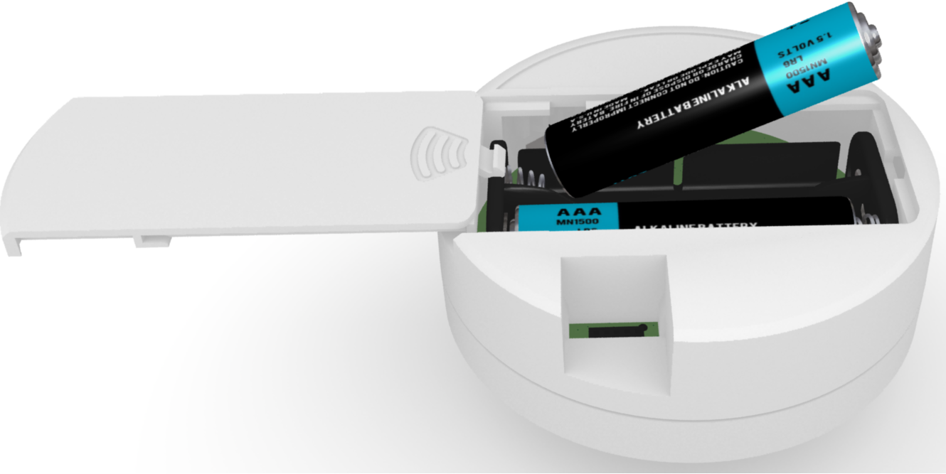
Figure 5 Battery Connection
If the IoT MSK is powered using JTAG:
- Plug in the USB cable to the micro-USB header on the communication interface board (CIB). The other side of the USB cable can be connected to a PC.
- Set the MSK side switch to OFF to cut off the battery and turn the CIB switch SW2 to ON to provide power to the MSK.
- Connect an IDC-10 cable to the 1.27 mm pitch header (10) on the CIB. Connect the other end of the IDC-10 cable to the debugging port on the bottom of the DA14585 IoT MSK.
The connection between the CIB and DA14585 IoT MSK is shown in Figure 6.
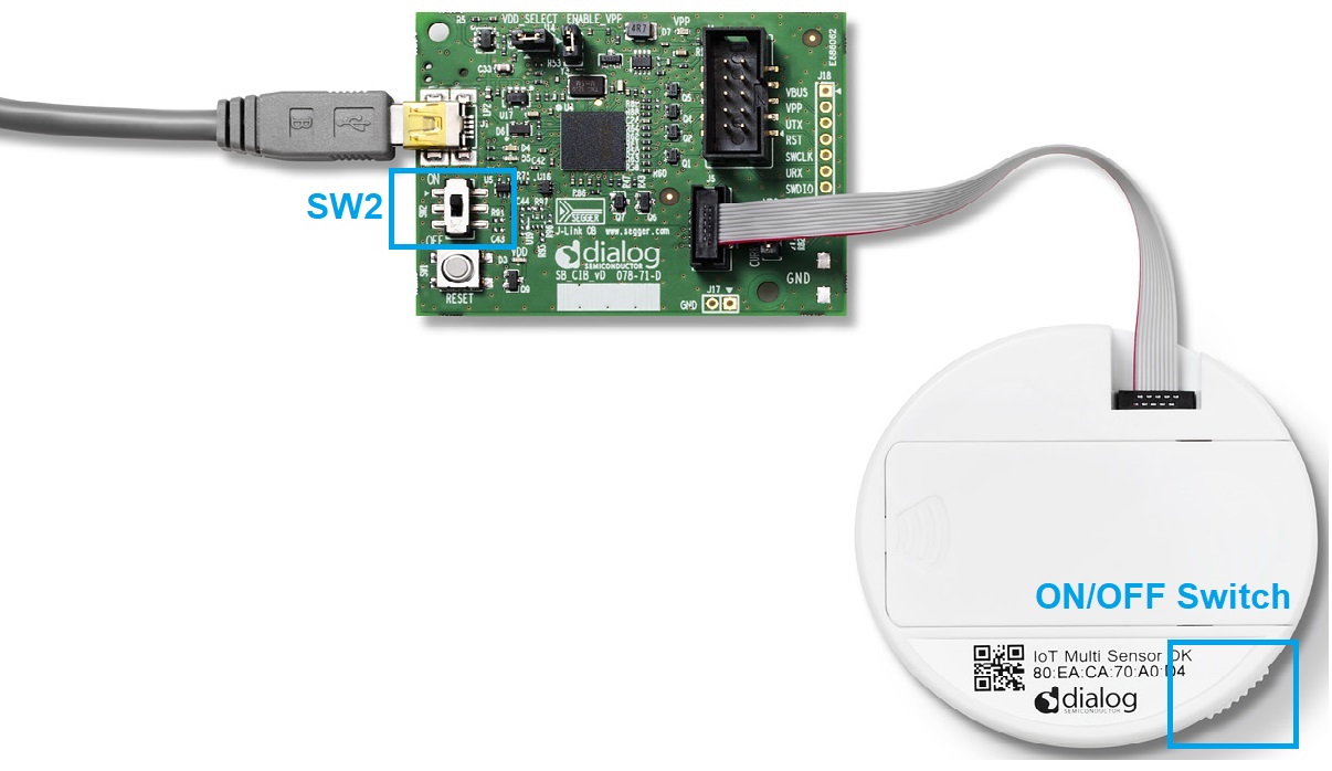
Figure 6 Connection between DA14585 IoT MSK and the CIB
The CIB implements USB-to-JTAG and USB-to-UART functions as shown in Figure 7.
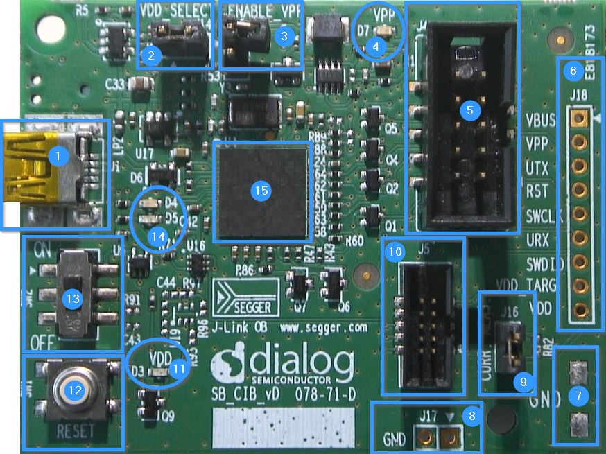
Figure 7 Communication Interface Board Layout
| Reference | Description |
|---|---|
| 1 | Mini USB Connector |
| 2 | VDD select, 1.8 V or 3 V |
| 3 | VPP enable (6.8 V) |
| 4 | VPP LED indicator |
| 5 | Target board connection header (2.54 mm pitch) |
| 6 | Output signals |
| 7, 8 | GND support points |
| 9 | Current measurement point |
| 10 | Target board connection header (1.27 mm pitch) |
| 11 | VDD LED indicator |
| 12 | Reset button |
| 13 | VDD ON/OFF switch |
| 14 | MCU LED indicator |
| 15 | MCU with Segger license |
Note
For further reading, more information about the CIB, refer to Communication Interface Board User Manual, UM-B-065