3. CodeLess examples
3.1. GPIO Pin references
- A port pin is referenced as a 2 digit decimal number:
- First digit is the port number, second digit is the pin number
- Port 1, pin 3 (P1_3) is thus referenced ‘13’
- Port 0, pin 6 (P0_6) is referenced ‘06’ or simply ‘6’
Example:
Setting P0_3 as an input with pull-up (GPIO type 2):
AT+IOCFG=3,2
Note
P0_4 and P0_5 are used for the UART interface and cannot be assigned to other functions! Only ports P0_0 to P0_3 can be used as analog inputs.
3.2. Simple tests
- You can begin with first example wherein you send “AT” as a command on the terminal and you receive “OK”. This verifies that the connection is established.
- “ATI” will give you the CodeLess version and type description
- “AT+BDADDR” will display your BD Address as show in Fig. 17.
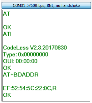
Fig. 17 Simple tests
- Refer to Table 1 for detailed commands syntax
Note
Please make sure you use CAPS for the commands as they are case-sensitive
Note
When you enter the AT commands, do not add space at the end of command
3.3. Examples - Local Board
3.3.1. Toggle LED
AT commands:
AT (To verify the connection by getting an “OK” back)
AT+IOCFG=10,4 (‘10’ implies Port 1, Pin 0 ; ‘4’ implies IO Functionality where 4 here means IO Output)
AT+IO=10,1 (AT+IO=10,0 for LED OFF)
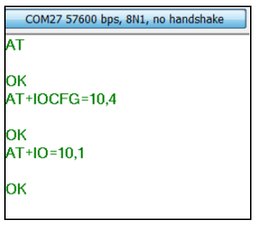
Fig. 18 Toggle LED
User LED D3 is toggled
Note
On both basic and pro kits, make sure the J9 jumper is connected.
3.3.2. Read ADC (here the analog input is connected to 3V supply)
Connect the P0_2 and VBAT_580 as shown in the figure. Once it is connected, send the following AT commands:
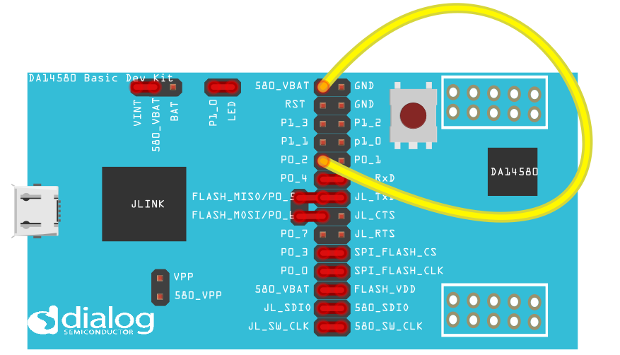
Fig. 19 Read ADC Setup
AT
AT+IOCFG=2,6 (P0_2, 6 implies analog input)
AT+ADC=2 (Reading the value from P0_2)
The ADC value shows 904 (10-bit ADC value) which can be converted to Voltage value by doing the following:

Fig. 20 ADC Calculation
You could connect an analog voltage from an external source and do the experiment again. This way you can verify what voltage you are measuring as compared to the input supply.
Note
The ADC value can range between 900~930 for a 3V voltage on the ADC input.
3.3.3. Write/Read I2C
We will be using the Adafruit MCP9808 I2C Temperature sensor to read the temperature value. The connections are as shown in figure 14.
- Vdd <-> VBat
- Gnd <-> Gnd
- SCL <-> P1_1
- SDA <-> P0_2
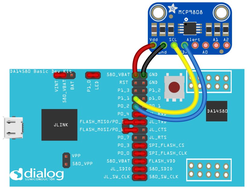
Fig. 21 I2C hardware setup
- AT+IOCFG=11,7 (Pin P1_1 represented here as “11” is used as SCL, “7” is Hardware AT command for I2C CLK … refer AT Commands section )
- AT+IOCFG=2,8 (Pin 0_2 , “8” is Hardware AT command for I2C SDA)
- AT+I2CSCAN (This gives you the sensor slave address, seen here as 0x18)
- AT+I2CCFG=7,400,16 (The slave addressing bit count: ‘7’ for 7bit or ‘10’ for 10bit; The bit rate: ‘100’ for 100kbit/s or ‘400’ for 400kbit/s; The slave register width: ‘8’ for 8bit or ‘16’ for 16bit.)
- AT+I2CREAD=0x18,5 (read the sensor at hardware address 0x18, register 5)
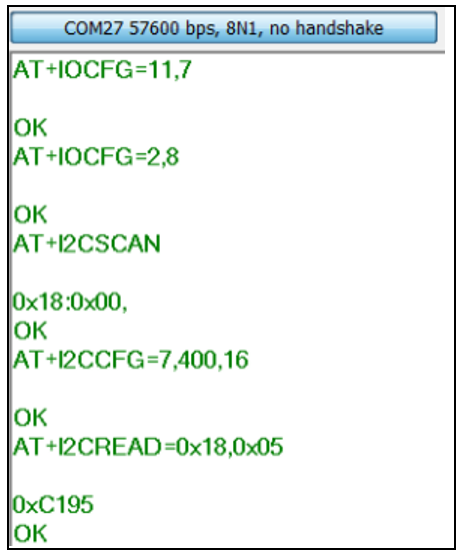
Fig. 22 I2C terminal
We receive a reading of 0xC195 which translates to 25.3°C
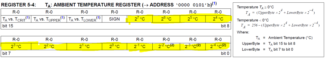
Fig. 23 I2C Temperature calculation (Source: MCP9808 Datasheet)
- Calculation :
Ta = (upper byte * 16 + lower byte/16)
Ta = (1 * 16 + 149 / 16)
Ta= 25.3°C
3.3.4. Command sequencer
Commands can be stored in command slots and triggered either by at command or by a timer. The following is a blinky example that toggles the on board led of basic kit every 1 sec
- AT+IOCFG=10,4 (Setup pin 10 as gpio output)
- AT+CMDSTORE=0,AT+IO=10,1;AT+TMRSTART=0,1,100 (command slot 0:Turn led on and after 1 sec run command slot 1)
- AT+CMDSTORE=1,AT+IO=10,0;AT+TMRSTART=1,0,100 (command slot 1:Turn led off and after 1 sec run command slot 0)
- AT+CMDPLAY=0 (Trigger command sequence in command slot 0)
3.4. Examples - Remote Board
Setup :
- Connect another Pro-Kit via USB to the PC
- As before, make a note of the COM ports from device manager
- Note the BD Address of both the boards
- Remote AT commands can be executed from the server as well as from the client side.
Note
Take a note of “r” in the AT commands. It indicates that you are referring to the remote board
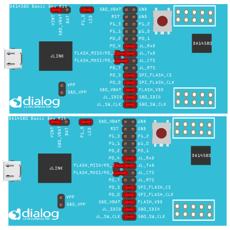
Fig. 24 Remote Example setup
3.4.1. Advertise/ Scan
Follow the set of AT commands to scan and connect to the peripheral device
- AT+ADVSTOP
- AT+CENTRAL
- AT+GAPSCAN
- AT+GAPCONNECT=<BD_address_of_peripheral>,R
- ATrI (‘r’ here implies remote board)
Note
From the fig 18 DF:CF:E7:66:8D:6C,R where the 6 bytes indicates unique BD Address of your device and the R implies Random address.*
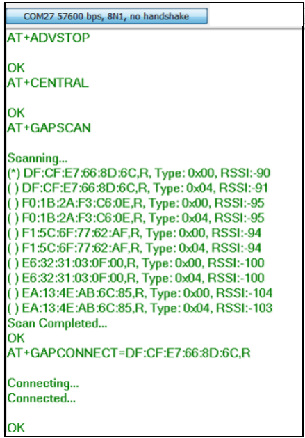
Fig. 25 Remote - GAP Scan and connect
3.4.2. Blink LED
The set of AT commands listed below will scan and connect to your peripheral device and blink the LED
AT commands:
- AT+ADVSTOP
- AT+CENTRAL
- AT+GAPSCAN
- AT+GAPCONNECT=<BD_address_of_peripheral>,R
- ATrI
- ATr+IOCFG=10,4
- ATr+IO=10,1 (Switches on LED D3)
- ATr+IO=10,0 (Switches off LED D3)
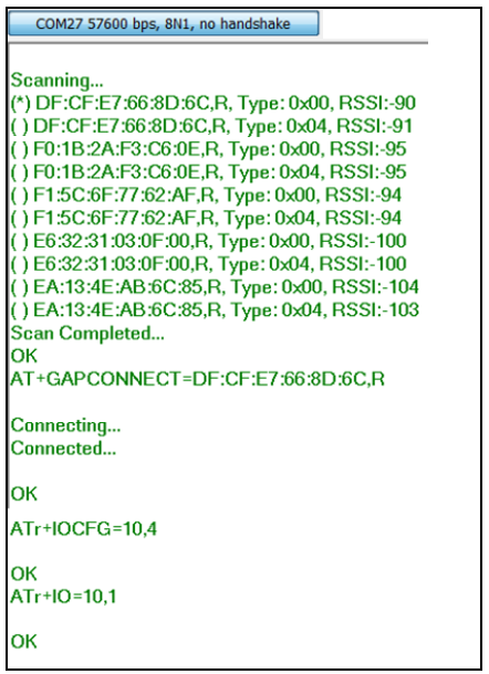
Fig. 26 Remote - Blink LED
3.4.3. Write/Read I2C
Setup - The connections are similar to the ones already done for the Local Examples. You can refer this figure to do the connections.
Fig. 27 Remote - I2C setup
AT commands:
- AT+ADVSTOP
- AT+CENTRAL
- AT+GAPSCAN
- AT+GAPCONNECT = <BD_address_of_peripheral>
- ATrI
- ATr+IOCFG=11,7
- ATr+IOCFG=2,8
- ATr+I2CSCAN
- ATr+I2CCFG=7,400,16
- ATr+I2CREAD=0x18,5
We receive a reading of 0xC170 which translates to 23°C. The calculations are done in similar way as done for the local I2C example.
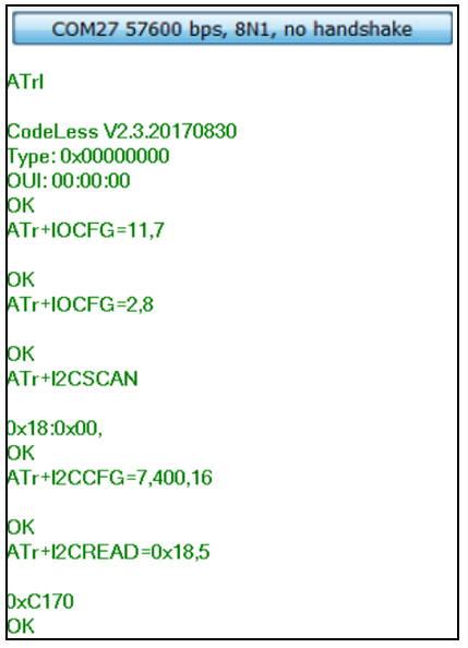
Fig. 28 Remote - I2C
3.4.4. Read ADC
The connections are as shown in the figure and is similar to the Local exmaple.
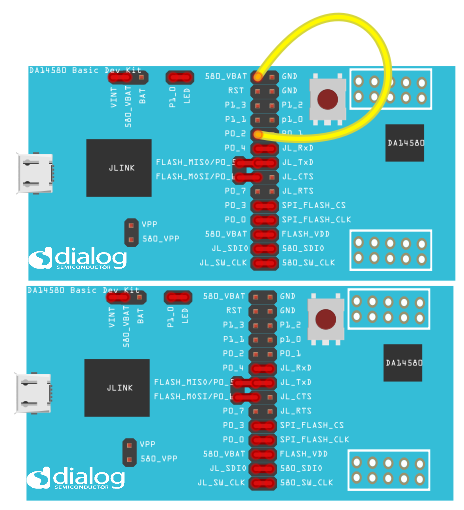
Fig. 29 Remote - ADC
AT commands:
- AT+ADVSTOP
- AT+CENTRAL
- AT+GAPSCAN
- AT+GAPCONNECT=<BD_address_of_peripheral>,R
- ATrI
- ATr+IOCFG=2,6 (ADC on P0_2)
- ATr+ADC=2
The ADC value shows 915(10-bit ADC value) which can be converted to Voltage value 2.951V.
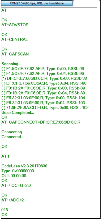
Fig. 30 Remote - ADC